Sponsored
JXB Performance Driveshaft Center Support Bearing Upgrade preorder now
Superspirit
Well-Known Member
Wow that's pricey. I specd one out for my truck and it wasn t far from what I paid for a 1 piece shaft.
Stevedbvik1
Well-Known Member
I’m going with this. I have a Tremor and there’s no one piece driveshaft for them. Next best thing. Good time to do the boot and lube on the slip yoke while installing this.
RedlandRanger
Moderator
I was going to say - you aren't far from a 1 piece driveshaft with that - If I ever need this, I'll probably go the one piece driveshaft route - I'd much prefer that than the 2 piece.Wow that's pricey. I specd one out for my truck and it wasn t far from what I paid for a 1 piece shaft.
21rangerCactus
Well-Known Member
I guess it depends if your lifted. My truck is leveled so I don't need the spacer kit. I don't need street and track, just street. I think I'll skip out on the bearing. So it's $229 plus shipping vs $729 plus shipping for the driveshaft.
I drive on the hwy a lot and the steel shaft mph limit is cutting it to close for me.
I drive on the hwy a lot and the steel shaft mph limit is cutting it to close for me.
Racket
Well-Known Member
- First Name
- John
- Joined
- Jan 21, 2020
- Threads
- 22
- Messages
- 2,206
- Reaction score
- 3,410
- Location
- Here and There
- Vehicle(s)
- 2019 Lariat Supercrew 2WD
- Occupation
- Transient
Great. Another component upgrade I didn't know I would consider.

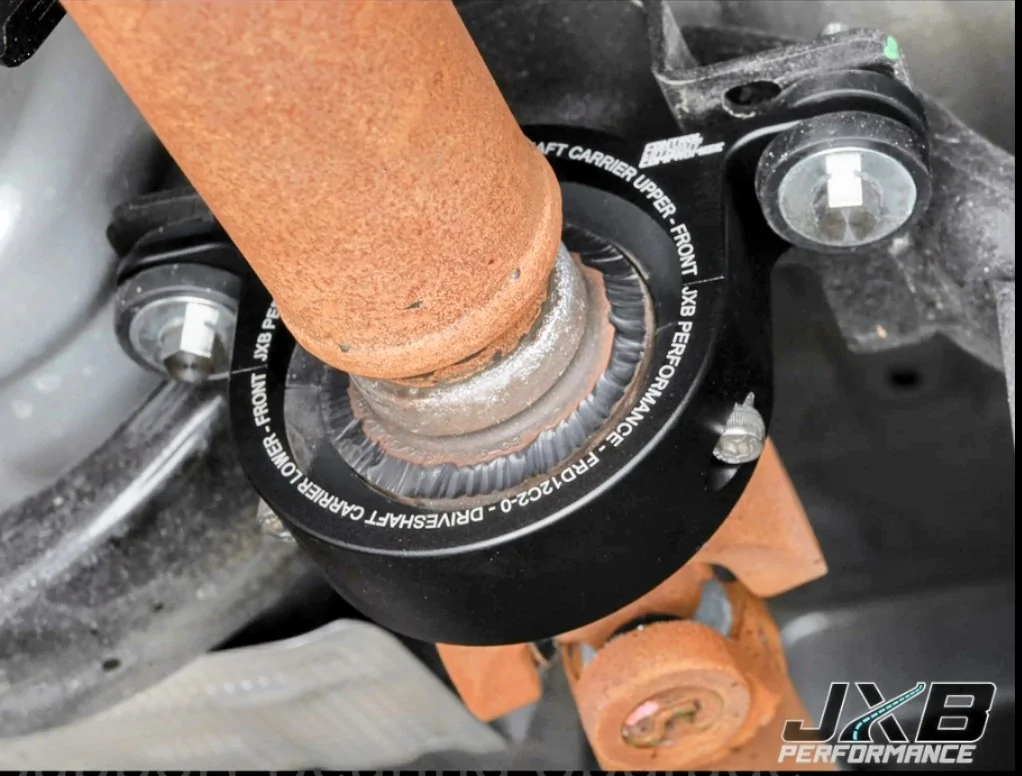
Then the cool custom version using the existing bearing and bushing isolated from the frame.
Your mechanic might be impressed if they are looking

(What's up with the surface rust?)
And a video on installing:
So I don't know? Would this refine the driving experience noticeably on my daily driver? My best guess is maybe, even if it were a placebo effect.
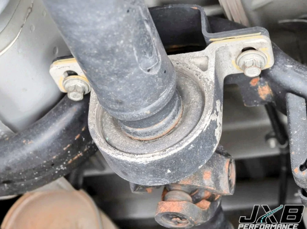
They show the factory bearing support (solid mounted)Benefits as described by our customers include:
- Smoother low-speed on/off throttle behavior off-road
- More direct throttle response
- Firmer, more direct shifts
- More instantaneous launches
- Reduction in vibration due to driveshaft misalignment and/or rubber deterioration
Then the cool custom version using the existing bearing and bushing isolated from the frame.
Your mechanic might be impressed if they are looking
(What's up with the surface rust?)
And a video on installing:
So I don't know? Would this refine the driving experience noticeably on my daily driver? My best guess is maybe, even if it were a placebo effect.
Last edited:
Rrrr-Anger19
Well-Known Member
I get extreme angles are bad for driveshafts, but if lifts beyond 2.5" represent less than 7% of the community and maybe 35% of owners are level with a 2.5" lift
what specific situation would this be a pivotal requirement?
what specific situation would this be a pivotal requirement?
Stevedbvik1
Well-Known Member
You have to do science. Then figure out which thickness spacers get you to your target.How would you know how many of the supplied spacers to use for a lifted vehicle!? That’s the part where I got lost

To figure out the driveline angles for a two-piece driveshaft, you must
measure the slope of each individual component (transmission output, front driveshaft section, rear driveshaft section, and pinion shaft) and then calculate the difference between them to find the operating angle of each U-joint.
For a smooth, vibration-free driveline, the goal is to keep each individual U-joint operating angle between 0.5° and 3.0°.
1. Preparation
- Ride Height: The vehicle must be on a level surface with its full weight on the suspension (tires on the ground or a drive-on lift). Measuring while the vehicle is jacked up will give you inaccurate results because the suspension geometry is not at its operating position.
- Tools: Use a reliable digital angle finder (accurate to at least 0.25°).
- Consistency: Always measure from the same side of the vehicle (e.g., the driver’s side) to ensure your "up/down" slope readings remain consistent.
2. Measuring the Slopes
Measure the slope of each component. If possible, place your angle finder on the flat, machined surfaces of the yokes or the transmission output shaft. If the driveshaft is in the way, you may need to rotate it so a bearing cap is accessible.
- Transmission Output Shaft: Measure the slope. Note if it is "up" or "down" relative to the horizon.
- First Driveshaft Section: Measure the slope of this tube.
- Second (Rear) Driveshaft Section: Measure the slope of this tube.
- Pinion Shaft: Measure the flat surface on the pinion yoke.
3. Calculating the Operating Angles
The operating angle is the difference between the slopes of two connected components. When looking from the side:
- Same direction: If both slopes are "down" (or both are "up"), subtract the smaller number from the larger number.
- Example: Trans output is 4° down, front shaft is 2° down. Operating angle = .
- Opposite directions: If one is "down" and the other is "up," add them together.
- Example: Front shaft is 2° down, pinion shaft is 2° up. Operating angle = (This would be too high).
4. Key Principles for Two-Piece Systems
- The 3-Degree Rule: Keep every individual U-joint operating angle under 3.0°.
- Minimum Angle: Do not aim for 0°. A minimum of 0.5° is required to ensure the needle bearings inside the U-joint rotate; otherwise, they will brinell (dent) and fail prematurely.
- Parallelism: Ideally, the transmission output shaft and the differential pinion shaft should be parallel to each other to help cancel out vibrations.
- Center Support: Ensure the carrier bearing (center support) is properly shimmed so that the first section of the shaft is correctly aligned. The front U-joint (at the transmission) should ideally have a slight operating angle between 0.5° and 1.5°.


Superspirit
Well-Known Member
I have a 2.5 inch lift with the bilstein 5100's row rear springs and the vibrations were so bad I had to put a 1 piece shaft in. So with Shims and bearings this was $379 ish I said now only paid. $700 for the whole shaft. So that's my thoughts
Dr3wDrop
Well-Known Member
That’s too much work roflYou have to do science. Then figure out which thickness spacers get you to your target.
To figure out the driveline angles for a two-piece driveshaft, you must
measure the slope of each individual component (transmission output, front driveshaft section, rear driveshaft section, and pinion shaft) and then calculate the difference between them to find the operating angle of each U-joint.
For a smooth, vibration-free driveline, the goal is to keep each individual U-joint operating angle between 0.5° and 3.0°.
1. Preparation
- Ride Height: The vehicle must be on a level surface with its full weight on the suspension (tires on the ground or a drive-on lift). Measuring while the vehicle is jacked up will give you inaccurate results because the suspension geometry is not at its operating position.
- Tools: Use a reliable digital angle finder (accurate to at least 0.25°).
- Consistency: Always measure from the same side of the vehicle (e.g., the driver’s side) to ensure your "up/down" slope readings remain consistent.
2. Measuring the Slopes
Measure the slope of each component. If possible, place your angle finder on the flat, machined surfaces of the yokes or the transmission output shaft. If the driveshaft is in the way, you may need to rotate it so a bearing cap is accessible.
- Transmission Output Shaft: Measure the slope. Note if it is "up" or "down" relative to the horizon.
- First Driveshaft Section: Measure the slope of this tube.
- Second (Rear) Driveshaft Section: Measure the slope of this tube.
- Pinion Shaft: Measure the flat surface on the pinion yoke.
3. Calculating the Operating Angles
The operating angle is the difference between the slopes of two connected components. When looking from the side:
- Same direction: If both slopes are "down" (or both are "up"), subtractthe smaller number from the larger number.
- Example: Trans output is 4° down, front shaft is 2° down. Operating angle = .
- Opposite directions: If one is "down" and the other is "up," addthem together.
- Example: Front shaft is 2° down, pinion shaft is 2° up. Operating angle = (This would be too high).
4. Key Principles for Two-Piece Systems
- The 3-Degree Rule: Keep every individual U-joint operating angle under 3.0°.
- Minimum Angle: Do not aim for 0°. A minimum of 0.5° is required to ensure the needle bearings inside the U-joint rotate; otherwise, they will brinell (dent) and fail prematurely.
- Parallelism: Ideally, the transmission output shaft and the differential pinion shaft should be parallel to each other to help cancel out vibrations.
- Center Support: Ensure the carrier bearing (center support) is properly shimmed so that the first section of the shaft is correctly aligned. The front U-joint (at the transmission) should ideally have a slight operating angle between 0.5° and 1.5°.

Stevedbvik1
Well-Known Member
Technically you’re supposed to do that when you lift the truck to reset proper driveline angles even if it’s a one piece driveshaft. Shimming would be at the rear axle instead of the carrier bearingThat’s too much work rofl
21rangerCactus
Well-Known Member
Yeah not many people know that.Technically you’re supposed to do that when you lift the truck to reset proper driveline angles even if it’s a one piece driveshaft. Shimming would be at the rear axle instead of the carrier bearing
When I lowered my 4th gen fbody I bought an adjustable torque arm to line the rear end up properly. Many do without it but it helped tremendously in traction and having zero vibrations.
My 05 GTO is lowered and I switched to a once piece carbon driveshaft. I had the shop align my cradle.... Guess what? No vibrations. You'll see post after post "my gto has vibrations after switching to a one piece ds"
TJC
Well-Known Member
- First Name
- Tony
- Joined
- Aug 28, 2020
- Threads
- 45
- Messages
- 3,964
- Reaction score
- 9,991
- Location
- North Carolina
- Vehicle(s)
- 93 Miata, 05 Ranger 4x4, 20 Ranger 4x4, 23 CX-5
And I believe Ford allowance is 5.0°For a smooth, vibration-free driveline, the goal is to keep each individual U-joint operating angle between 0.5° and 3.0°.
...
...
- Parallelism: Ideally, the transmission output shaft and the differential pinion shaft should be parallel to each other to help cancel out vibrations.
- Center Support: Ensure the carrier bearing (center support) is properly shimmed so that the first section of the shaft is correctly aligned. The front U-joint (at the transmission) should ideally have a slight operating angle between 0.5° and 1.5°.....
Surprised? I am not.
Sponsored
Similar threads
- Replies
- 16
- Views
- 7,532