Big Blue
Well-Known Member
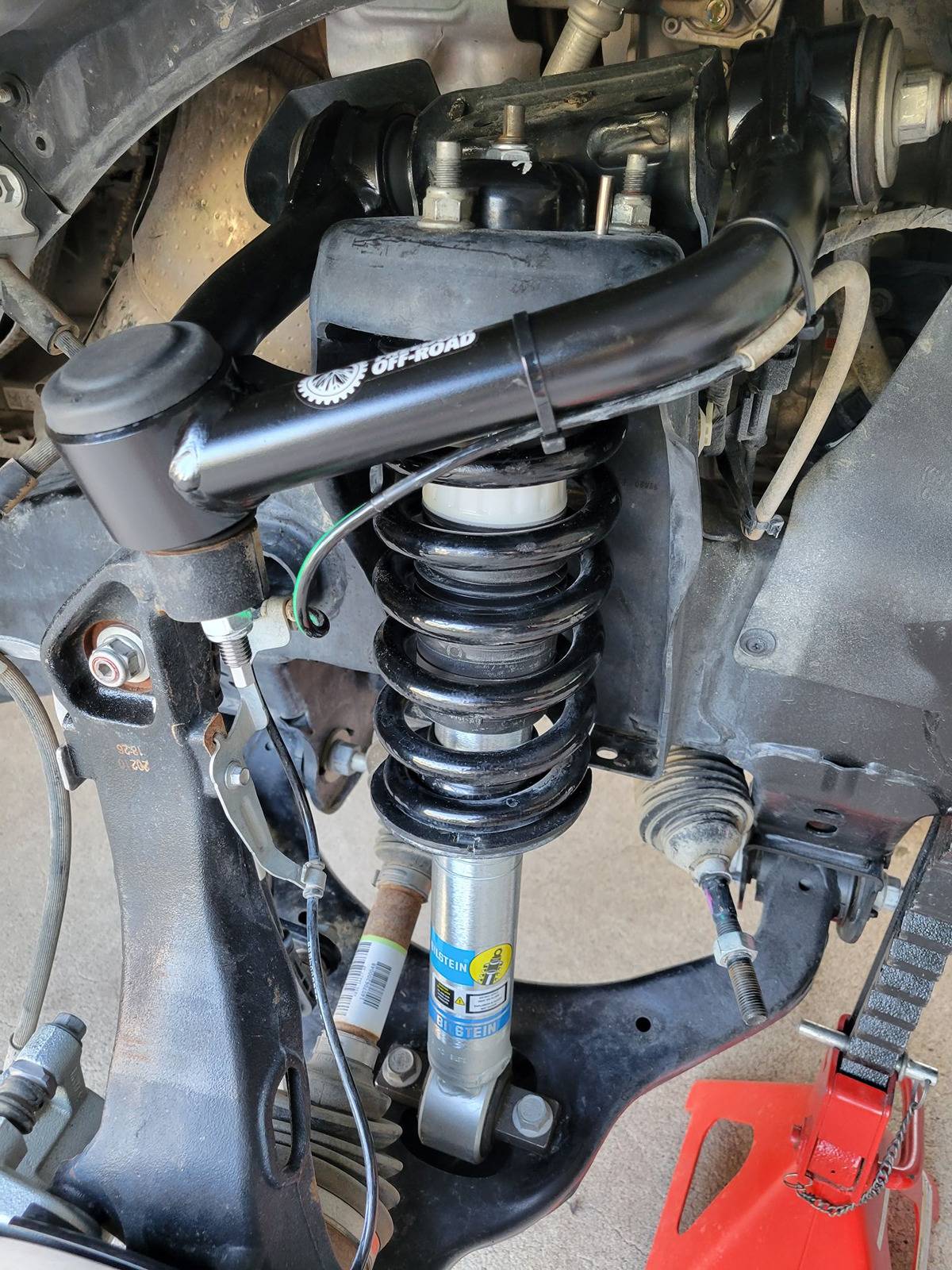
seriously I think you may be over thinking this. Or, maybe I am.Got both of the 5100's and upper control arms installed. Not all warm and fuzzy about them though. Height clip is in #5, or the top groove for 2.5" lift. With the jack stands under the frame rails, and a bottle jack next to the lower ball joint, so it's only an inch or so from the face of the rotor, the frame lifts off the jack stands with less than a quarter inch of lift at the jack.
This is NOT good. What it means is the shocks will be riding very close to the top end of shock travel under load. That means on the road any time the suspension is unloaded, even slightly, the shocks are going to hit the top of their travel.
You want at least a few inches of sag so the shocks will have enough travel in normal driving conditions as to not hit their end limits. I can see this setup hitting the top travel limit constantly.
The new 5100's are basically the same length as the OEM Fox shocks. So creating lift by moving the bottom spring mount higher just pushes the piston farther up the cartridge substantially reducing unload travel.
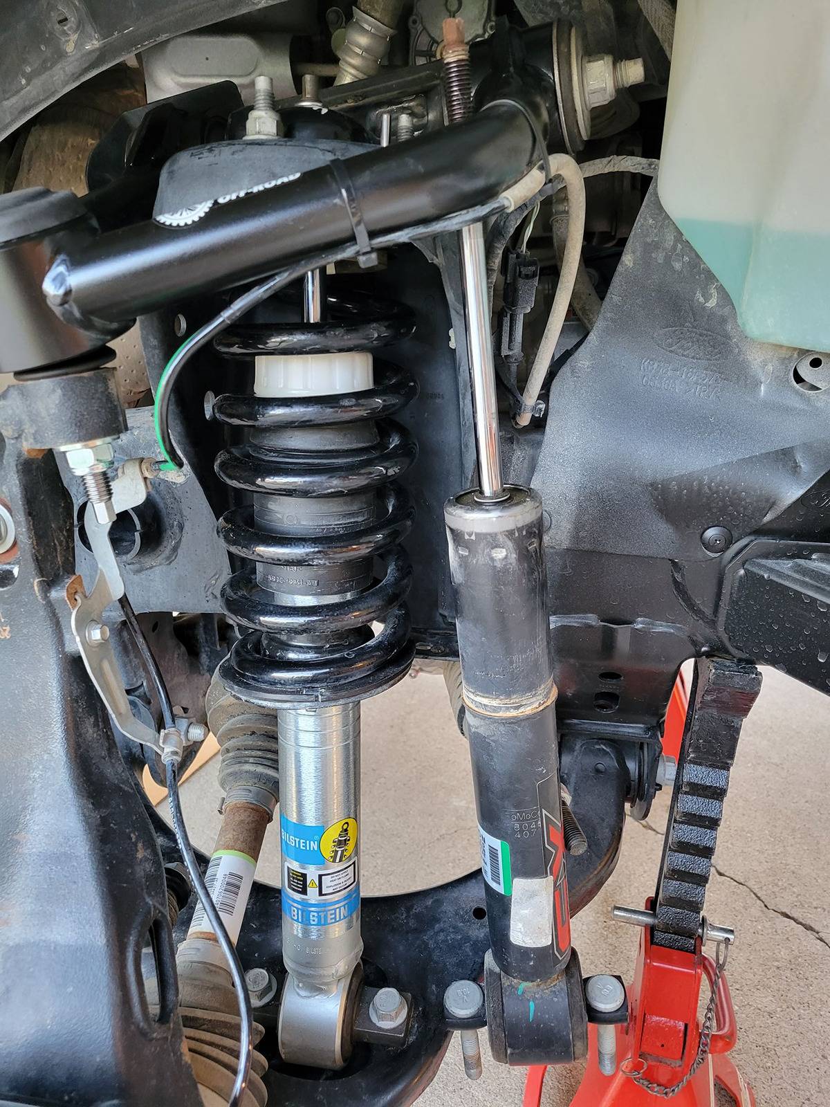
I just assumed that a company like Bilstein would have accounted for this. Apparently not. In order to lift the front end and keep enough travel both directions as to not hit the end limits, you need to move the center range of piston travel a length equal to the amount of lift in order to maintain full, equal piston travel. So if you don't have physically longer shocks, then a spacer is the only proper option to lift the front end and maintain proper shock travel.
I bought these from Stage-3 and will contact them to see what they say. But the only logical solution at this point to use them and still lift the front end is to move the lower spring seat clip down to the #1 groove, which is 0.0" lift, and install a spacer.
Removing the shocks, compressing the springs, changing configurations and reinstalling them is not a simple or easy job. I fought with the individual spring compressors because I figured this was a one time job. Just another smack in the face for the Salvage Ranger rebuild. I'm going to blow another $200 and get a professional spring compressor stand this time. After all, it's only money, blood, labor and time.

When you do a level on an IFS you are really not changing the amount or range of travel in the suspension. You are just changing where the "at rest" ride hight is. This changes the at rest geometry of the upper and lower control arms. This is why the need for different upper control arms. To get the alignment adjustments, mainly caster and camber, back into range. These measurements vary as the suspension travels through its range. So by doing a level you are actually giving up some droop (down travel) and adding some compression (up travel).
So, with the level that changes the lower spring perch on the shock, the at rest length of the shock will be changed . But, the shock mounting points remain the same. So the shock will see the same total travel through the full suspension travel.
A spacer level is a Little different in that it essentially lengthens the whole shock/spring stack with the spacer. This keeps the at rest position of the shock in relatively the same location, but runs the risk of bottoming the shock at full compression because you have essentially moved the upper mounting point of the shock down.
In either case the at rest length of the spring remains the same. As this is what it takes to support the front of the truck.
Sorry for the long post, but I wanted to explain what is going on with a level. A true lift is a little different, as it relocates all the suspension pivot points lower.
Now for your jack stand/bottle jack experiment. Without all front end components (weight), including bumper, on the vehicle and both sides being supported by the suspension it is impossible to get a reading where the at rest position will be in its range of travel. Many people have done levels like this and have not had issues.
Sponsored