airline tech
Well-Known Member
- Joined
- Aug 24, 2022
- Threads
- 28
- Messages
- 4,463
- Reaction score
- 8,536
- Location
- Midwest - KS
- Vehicle(s)
- 2022 Ranger Lariat-Super Crew, Cactus Gray
- Occupation
- Aircraft Tech
- Thread starter
- #1
Due to the number of issues and complaints for the HVAC (Climate Control System) I wanted to try to show and explain the operation of the system and breakdown how the internals work.
Since I do not have a spare HVAC Unit laying around, I have to do this with various online pics I found.
This is a Lengthy but Informative Thread:
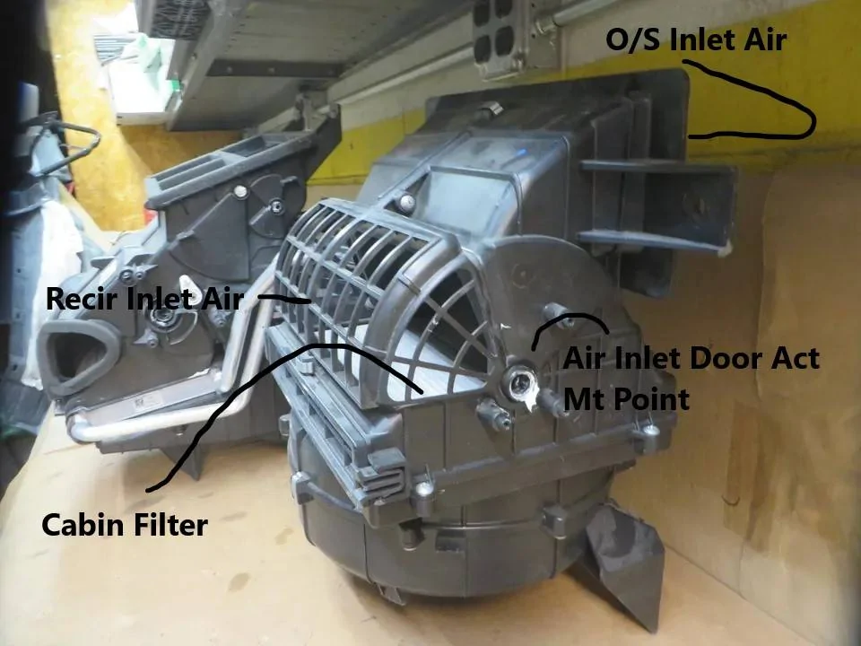
AIR INLET:
Let's start with the Air Inlet Door
This is mounted just behind the Glovebox just above the cabin filter.
This door is an annoying design for some, and it also allows an easy point of entry for mice into the cab.
NOTE: Even when in Recirculation Mode, the door is NEVER 100 % Closed, it is designed to remain 10% OPEN even when it is closed.
The system is designed to operate mostly with the Door Opened to allow maximum outside air to be introduced into the cab, even with the system off you still have outside fresh air entering the cab through the open vents in the pic.
Note: When the HVAC is OFF - You do not have any airflow from the cab vents, but you do have - Fresh Air Intake coming into the cab from the Recirculation Air -(Open) vents - since the Air Inlet Door closes when off, since the Blower Motor is not running to suck this air into the HVAC, it just pushes it out of this opening.
and uses this as Fresh Air (Intake) and the air Exhaust out of the (Rear Cab - Exhaust Vents)
Note: HVAC Off = System Turned Off
The Air Inlet Door Moves to Partially Open - When the Truck is turned off.
The issue with the design of it not going 100 % closed, it will always remain at least 10 % open (in recirculation mode) is that the design of the air inlet being so large that any (skunk smell, smelly exhaust or SMOKE from Wildfires can easily be sucked into the cab.
Even if you place the system in recirculation mode to lower the amount of Outside Air (Input) the system has an internal Timer that only allows the door to be in recirculation mode for (5-Minutes) then it automatically opens back up.
While I cannot state how this is annoying for SMOKE areas of the country, I have noticed that this truck will inhale every obscure smell it gets driven through.
Much GREATER than any vehicle I have ever owned.
When you turn the truck off, this door powers to the partially open position - reason to vent the HVAC Box (mainly the Evap Core) to eliminate musty stale odors from the EVAP core and to assist in drying and or evaporating any moisture in the Condensate Drain and Evap core area.
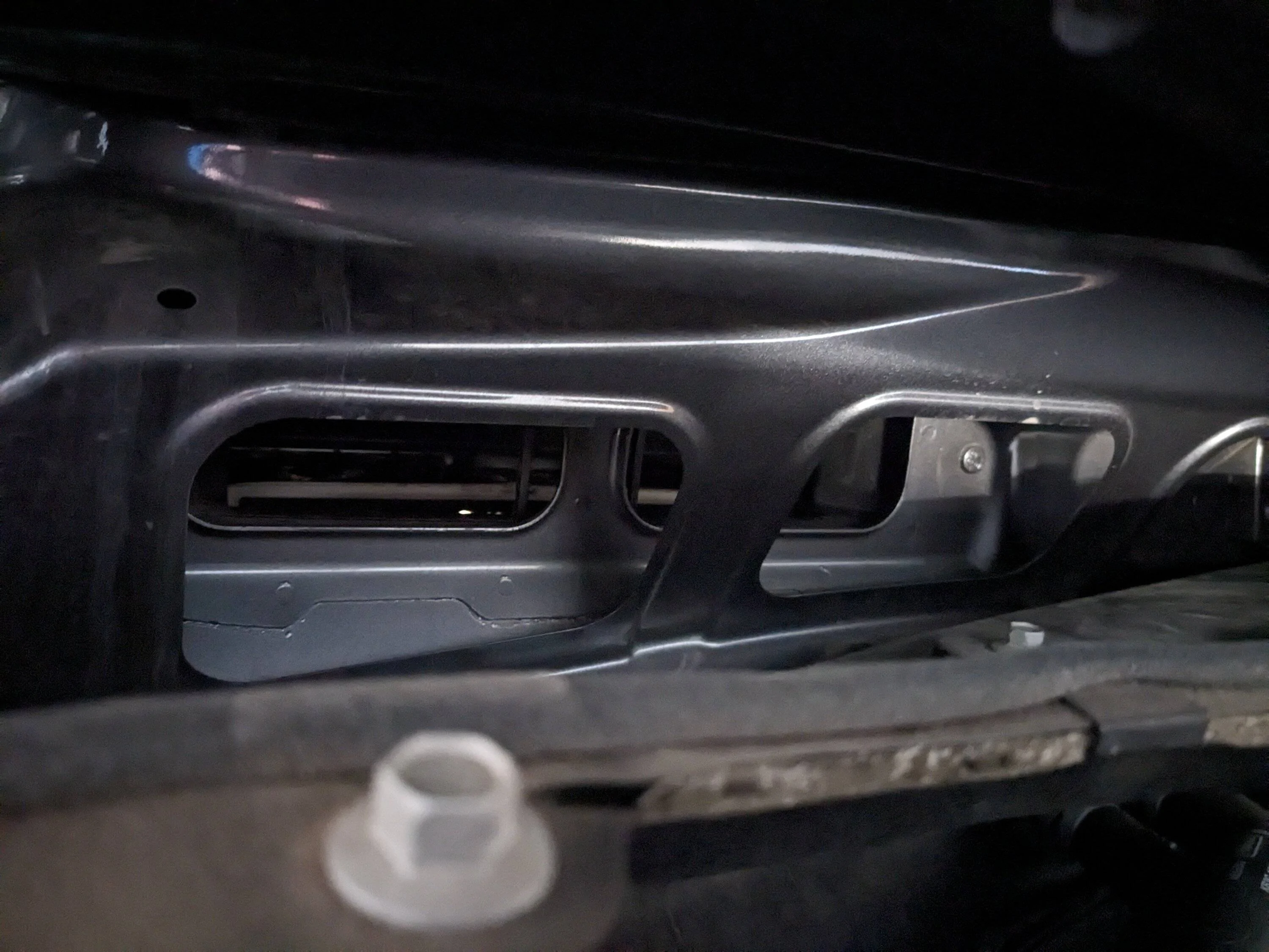
The issue with this (needed) design is the size of the vent openings and also the engineering design leaving out an important need and that is a screen on the outside inlet air end.
Mice can find their way down under the plastic cowling (below the windshield) and crawl into the inner (metal cowling) and then enter this inlet port and down on top of the Cabin Air Filter and then able to fit through the vent openings as viewed in the pic.
They now have full access to the cab and the tasty dash wiring.
I cover more details on how and when this door operates later.

Edit: Added Info and Pic
Pic Showing how the door moves to partially open with truck shut off.
Note the opening and entry point for mice.
This is the reason to add a screen under the cowl, to block this access off for mice.
To understand operation of the door:
Rotates CW - Recirculation (ON) - Closing the Outside Air but does not actually fully close 100% it only closes about 90%, leaving roughly about 10% of an opening for Outside Air to enter the cab.
Rotates CCW - Recirculation (OFF)

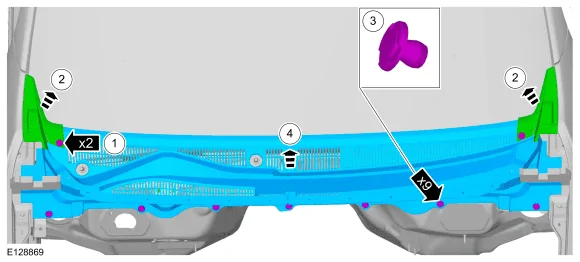
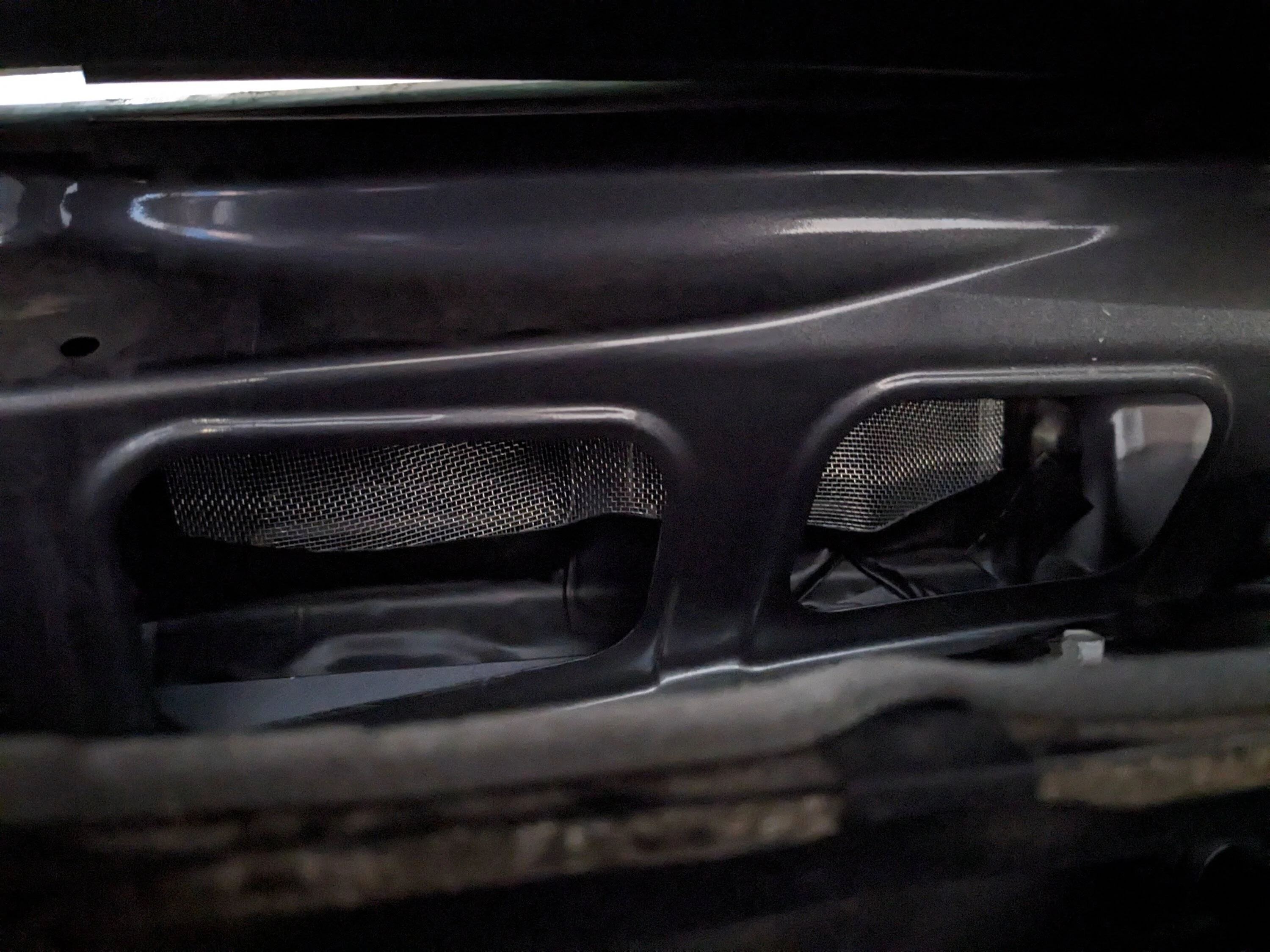
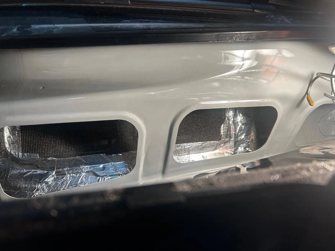
If you remove the Plastic Cowling under the Windshield, you will see this opening. This is the inlet to for the Outside Air into the HVAC Box. (Passenger Side)
You can cover this opening with a screen (I used Drywall Sanding Screen) 120 Grit.
This prevents mice and debris entry into the Cab.
This also helps slow down the Air Intake by providing (SOME) blockage but still allows airflow. Lessens the Fowl Odors be sucked in so quickly.
This has no effect on the Blower Motor - Operation.

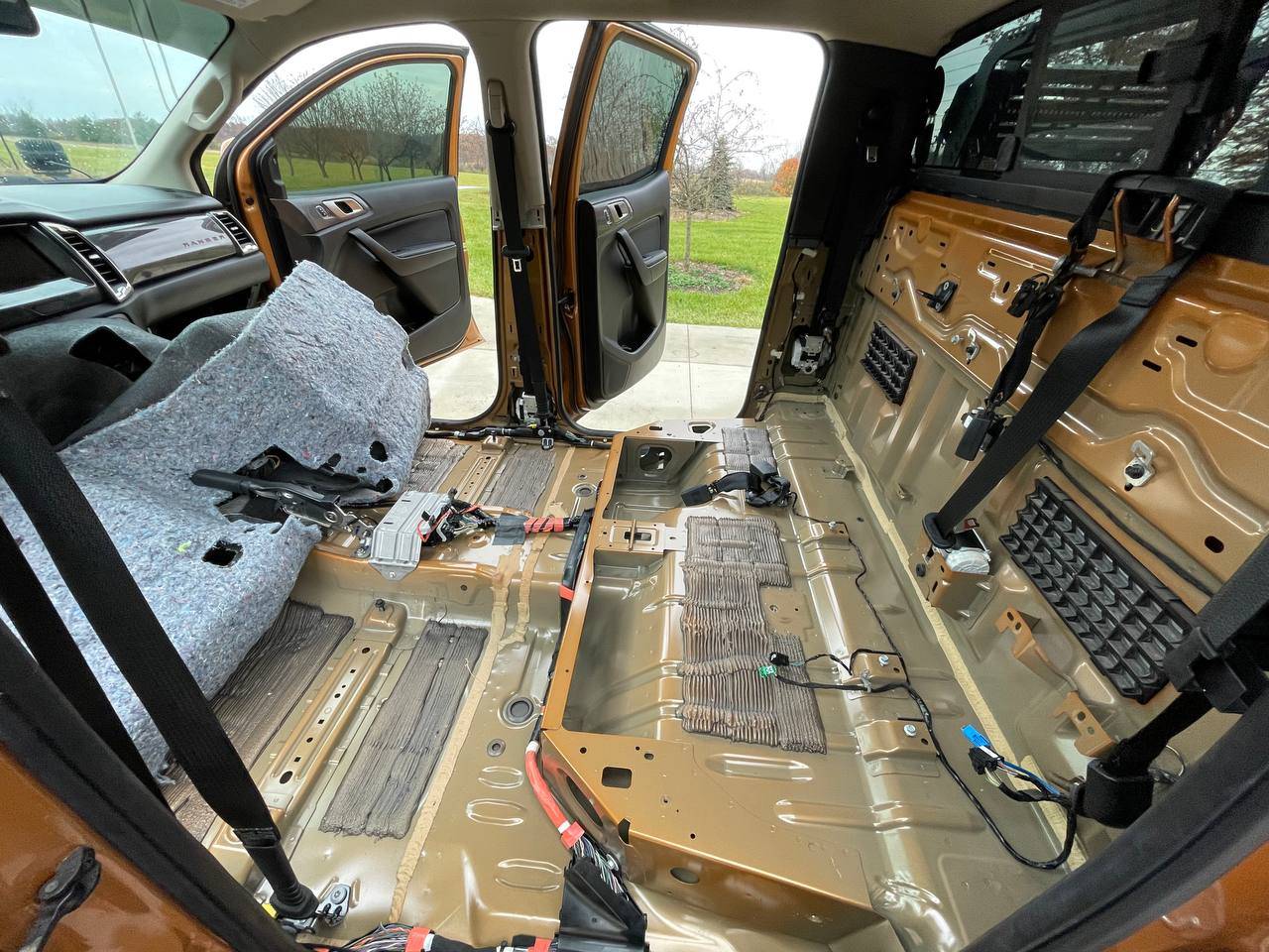
Pic showing Rear Cab - Exhaust Vents

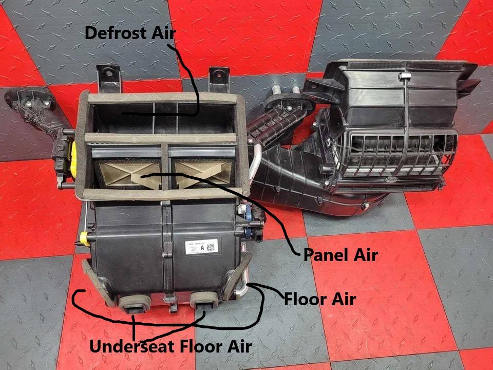
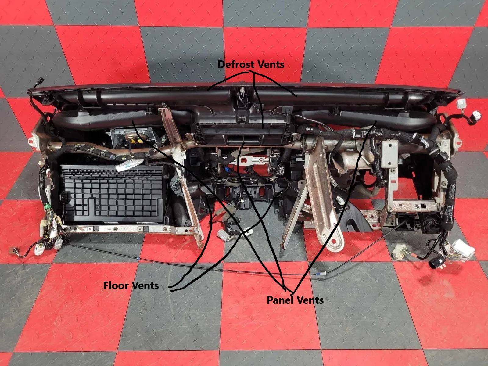
AIR DISTRUBUTION:
To help visualize how the system operates let's take a look at the air distribution.
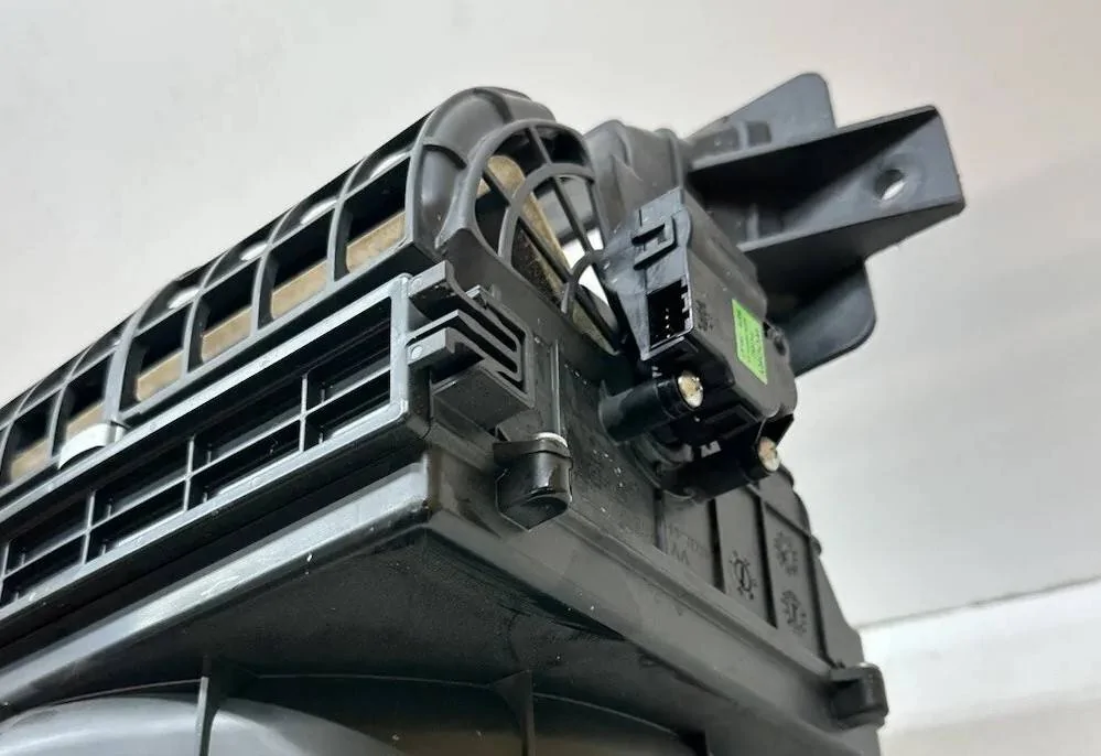
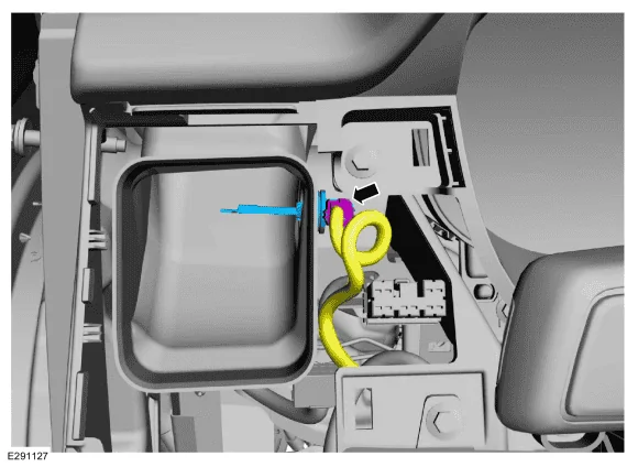
We have (1) Mode Door Actuator that controls (Moves) a Plastic Bell Crank (Yellow-Plastic Piece)
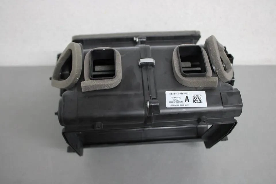
This moves 3 sets of Doors into position to distribute the selected airflow.
The visible doors in this pic show the Panel Air Doors
Note: For those that have issues with Foam pieces being blown out of the ducts / vents, if you look closely, you can see Foam around the Panel Vent Doors
There is Foam around the various doors and ducting to aid in sealing the system for airflow leaks.
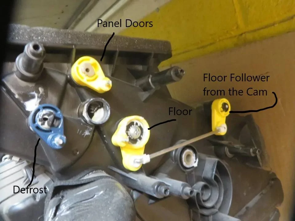
Here is a view from a removed Dash Console

Now this pic shows the layout of the door levers that are driven by the yellow bell crank.
Note: The Lever I have labeled Floor is just the Driving lever for the Floor Follower - The Floor Follower is the Lever that is actually moving the Floor & Under Seat Doors.
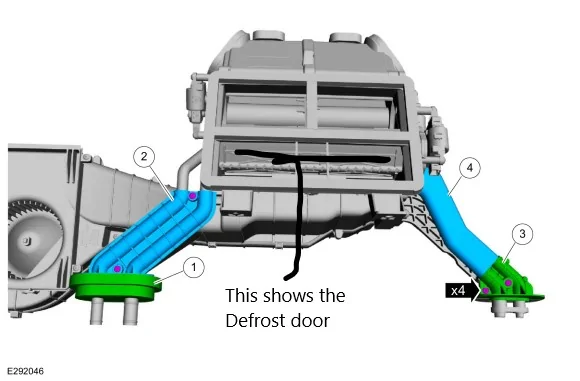
Here is a pic of the Bell Crank that is driven (moved) by the Mode Door Actuator
Note: I cannot find a pic of the actual bell crank that is installed in this location, but this gives a general idea on how they connect and move in unison as the actuator rotates.

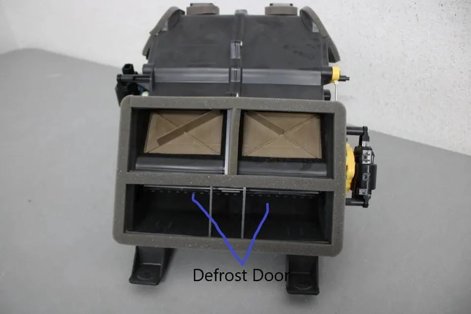
Pic Showing - Panel Airflow (Example) of how the doors move to close off the panel air.

Defrost Door - Driven by the Blue Lever

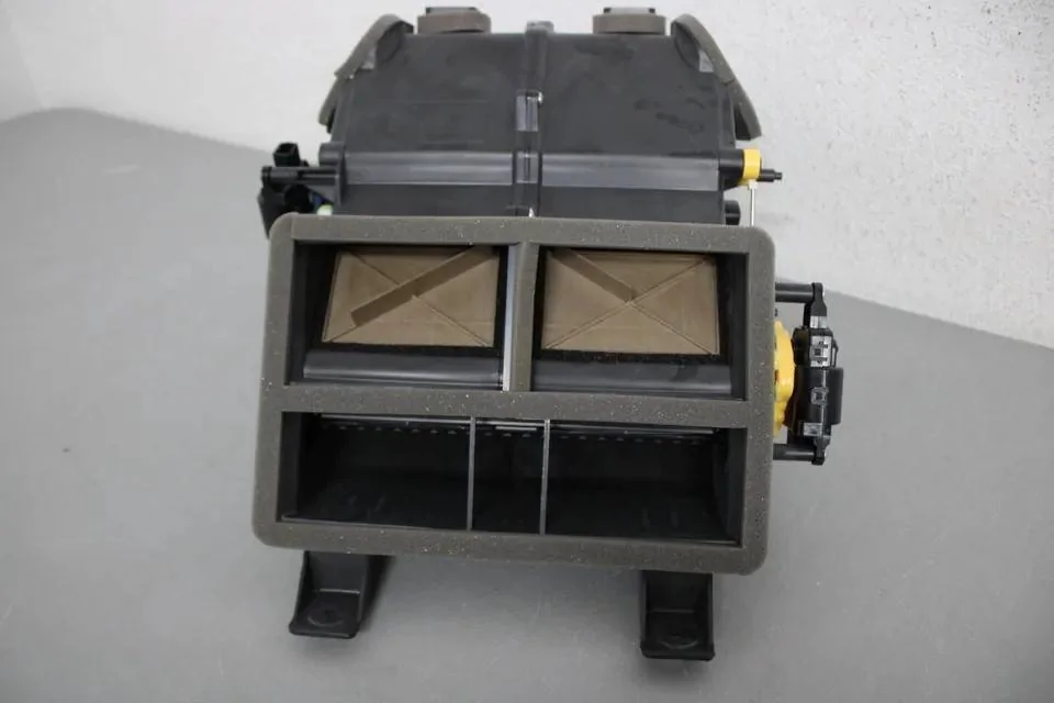
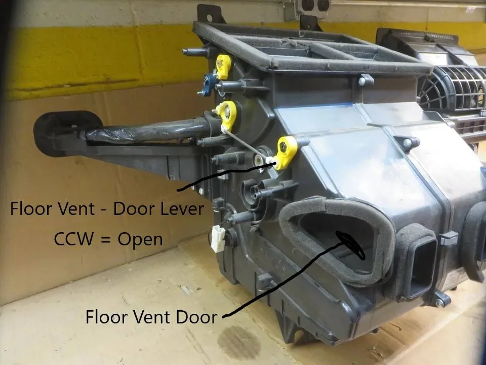
Here is a pic of the Floor Door, you can see it in the vent ports partially open position.
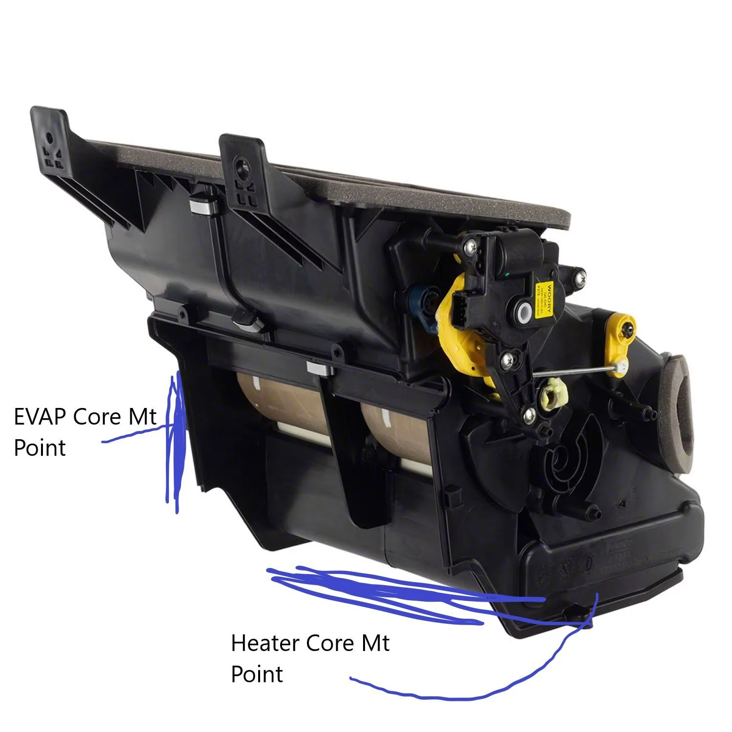
The Cutout at the bottom of the Unit is where the Heater Core Mounts
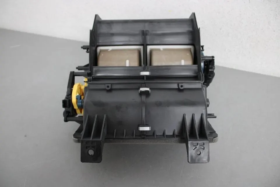
Here is a pic of the Floor Vent Door (Closed Position - No Airflow)
So, if you are in manual mode with Floor Selected, this will be open and if you are having weak airflow to the driver's floor duct above your foot then it is possible that the ductwork was kicked off and the air is coming out of this port instead of at the end of the duct above your foot.
Note: The Yellow lever just slightly above the outlet port, as the lever driven by the actuator cam rotates (CCW) the door is raised (Opened) to allow airflow to the Floor and Undereat Floor Vents
Basic Airflow to the Bottom of the Unit, then controlled by the various doors.
Note: The Location of the Heater Core
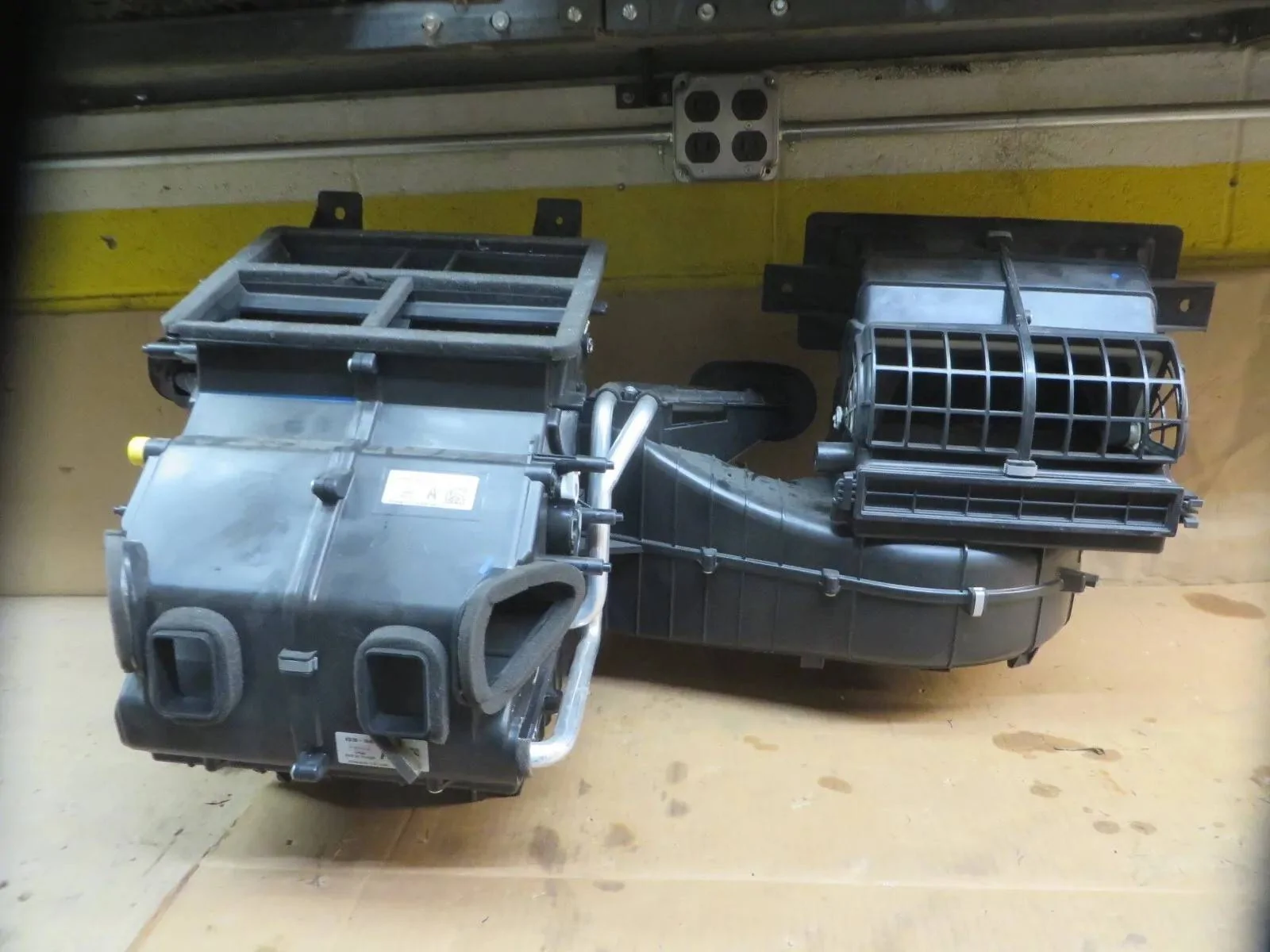
Picture this housing fully enclosed as it is mounted on the main unit.
There is constant airflow across the EVAP and Heater Core (at all times)
When MAX AC is selected the Heater Core is blocked, so you are bringing in outside air and blowing it across the cold EVAP Core.
The Temperature Doors automatically move to Full Cold (LO) and fully close (thus blocking heater core) airflow from entering the ductwork.
When AC is selected the airflow around the Heater Core is based on what you have (Temp Selected)
This uses both (Mixed/Blended) Airflow from the EVAP (Cold) and Heater Core (Heat) to get the desired output Temp selected.
When Heat is selected (The AC Compressor is OFF), so you will not have (Cold) airflow from the EVAP Core, and you will have only outside air blowing across the EVAP Core and Heater Core (Hot)
The Temperature Output depends on what you have selected, the Temperature Doors (Amount Opened) will dictate the amount of heat coming from the vents.
The Higher (Selected Temp) the greater the Temp Door is opened to get the heat from the Heater Core
Note: In Defrost Mode - If above 32 Deg F, the AC Compressor will operate to help in Defogging via removing moisture.
32 Deg F and below the AC Compressor - will NOT operate.
In Max Defrost Mode - The Temp is automatically selected to Full Hot (HI) so the Temperature Doors move to fully open position, allowing maximum heat to be pulled from the heater core.

Here we can see the Drivers & Passengers Temp Doors (Aka Blend Doors)
Dual Climate will have (2ea) Doors - With Individual Control
This pic shows (Electronic Manual Control) Single Zone
So Automatic (Dual Zone) will have 2 Temp Door Actuators mounted on each side (as depicted)
Single Zone - Has (1) Actuator mounted on the Pass Side and controls both doors via a Bell Crank driving a lever (similar to the blue lever pictured)
The White Lever off of the Passenger Single Zone actuator moves the Driver's Temp Door

Electronic Manual Control (Single Zone)
Example of Dual Automatic Control
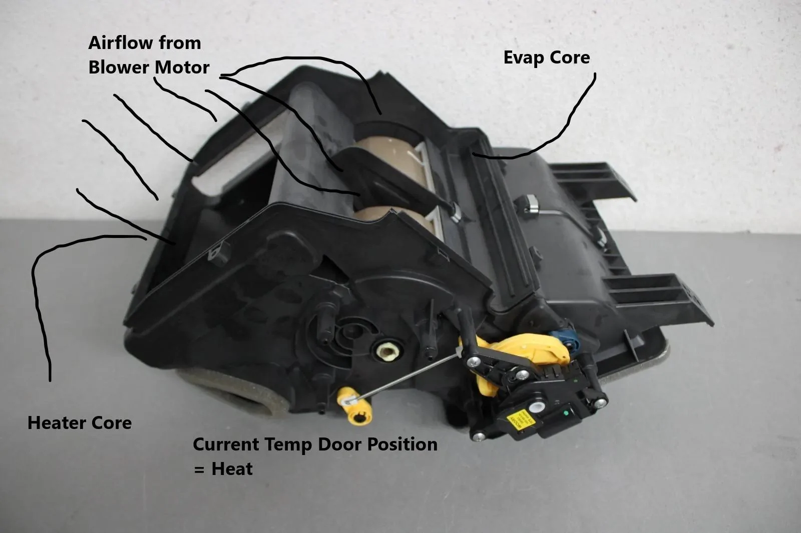
This shows where the Evaporator Core and the Heater Core, Mount to the HVAC Unit
This is how the Temp is regulated between the Cold and Heat
EVAP Core mounts to the Vertical
Heater Core mounts to the Bottom
If temps are not high enough for AC, then this would just be blended air coming from the Air Inlet and the amount the doors are open will dictate the amount of heat is allowed to be taken off of the heater core.
Airflow will travel around the heater core for heat.
or
Airflow will travel around the EVAP Core for AC
The (Open) amount of the Temp Doors adjusts the amount of Heated Air that is allowed into the duct work to the cabin.
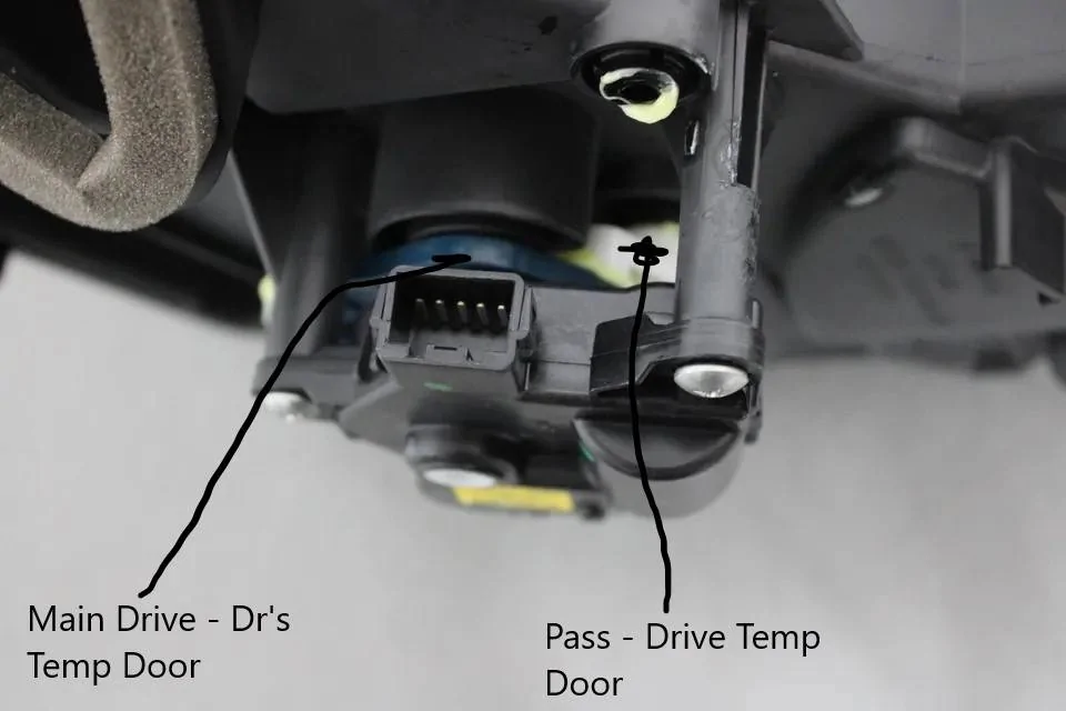
Now let's reference the SSM for the Popping and Clicking sound, this video shows the Temp Door Actuator (Bell Crank) jumped.
This Video shows the (Electronic Manual) Single Zone version of the HVAC, the main part of the actuator shaft drives the opposite door (Driver's) and the lever that is bound up drives the (on-side) door (Passenger) - So this would be a case of the Passenger Side Temp, not being able to control complaint along with the Snapping and Popping sound.
2019 Ford Ranger Heat Not Working - YouTube
There appears to be separate SSM's that cover the same issue
Edited for more details.
Released Jan 23, 2023 (Most Current)
SSM 51313 2019-2020 Ranger - Climate Control Temperature Will Not Adjust With Clicking/Snapping Noise From The Dash - Built On Or Before 30-Jul-2020 Some 2019-2020 Ranger vehicles built on or before 30-Jul-2020 may experience poor and/or no temperature change when the temperature is adjusted in the climate control system. There may also be a clicking/snapping noise from behind the instrument panel. Diagnostic trouble code (DTC) B1082 and/or B1081 may also be retrieved from the front controls interface module (FCIM). This may be due to an issue with the blend door and its controls. To avoid repeat repairs, replace the air distribution housing/heater assembly (service base part# 18478). Refer to Workshop Manual (WSM), Section 412-00. Do not replace the evaporator core for this condition. The WSM has been updated to reflect this change. For claiming use causal part 18478 and use applicable labor operations in Section 11 of the Service Labor Time Standards (SLTS) Manual
This SSM only replaces the Heater Core Control Box Assembly
Note: The whole assembly has to be removed to replace this part, so this SSM 51313 only saves money on the cost of the part but adds some labor time to disassemble the assembly to replace this part of the HVAC unit.
Being that this is the problem area, this is the reason for the change in replacement procedures.
This Part: - Current Price for Auto Temp Control = $198.00
Released Oct 15, 2020
SSM 49264: 2019-2020 Ranger - Climate Control Temperature Will Not Adjust With Clicking/Snapping Noise From The Dash - Built On Or Before 30-Jul-2020 Some 2019-2020 Ranger vehicles built on or before 30-Jul-2020 may experience poor and/or no temperature change when the temperature is adjusted in the climate control system. There may also be a clicking/snapping noise from behind the instrument panel. Diagnostic trouble code (DTC) B1082 and/or B1081 may also be retrieved from the front controls interface module (FCIM). This may be due to an issue with the blend door and its controls. To avoid repeat repairs, it is recommended to replace the climate control housing assembly (service base part# 18478). Refer to Workshop Manual, Section 412-00. Vehicles: 2019-2020 Ranger P375N USA (FG) Symptom Code: 111000 BODY PANELS/UNIBODY B1081 B1082
This SSM Replaced the whole assembly.
This Part: - Current Price for Auto Temp Control = $1091.00
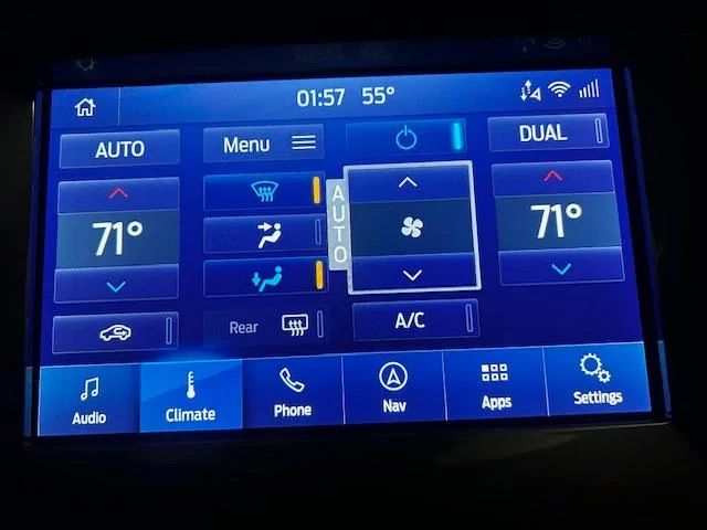
HVAC CONTROL:
Now we have covered the BASICS, Let's look at how we control it.
Let's look at Air Handling from the Control Head and where the air is distributed:
In the Selected Modes - This is where the air is distributed.
Note: Any air being delivered to the Floor Vents includes the Under Seat Vents
Note: When I state a VERY SMALL AMOUNT, it is just that, you can barely feel it, only a slight airflow is felt
Note: This airflow test was completed when in Manual Mode (Dual), Full Hot Temp Selected and Blower on High
Defrost:
Primary = Defrost Vents and Demist Vents (Strong Airflow) + Secondary = A Small Amount to the Floor Vents (Mild Airflow)
In Defrost Mode - The Air Inlet Door Opens and AC Compressor turns on (If above 32 Deg) via Ambient Temp Sensor (Input)
To remove humidity.
The Recirculation Button - Is DISABLED
Max Defrost:
The Blower Speed will automatically be commanded to High (Not Adjustable) and the Temp is automatically set to HI (Heat) and the Rear Window / Side Mirror Heat is automatically commanded ON.
The Air Inlet Door Opens and AC Compressor turns on (If above 32 Deg) via Ambient Temp Sensor (Input)
To remove humidity.
The Recirculation Button - Is DISABLED
AC:
The AC Button, can be selected and it will activate the AC Compressor clutch if above 32 Deg (Ambient - Outside Temp) and the Evap Core Temp is above 33.8 Deg.
Max AC:
The Air Inlet Door (Closes) - (Recirculation-Mode) - The Blower Motor speed is automatically commanded to HIGH, but can be manually adj to a lower setting and still remain in Max AC Mode. The Temperature is automatically set to full LO (Cold)
Panel:
Primary = Panel Vents (Strong Airflow) + Secondary = A VERY SMALL amount to the Defrost Vents Demist Vents and Floor Vents (Very Little Airflow)
The Recirculation button is enabled to allow you to press it to close the Air Inlet Door, but only for 5-Minutes, before it defaults back to open.
Floor:
Primary = Floor Vents (Strong Airflow) + Secondary = A VERY SMALL amount to the Defrost Vents Demist Vents and Floor Vents (Very Little Airflow)
The Recirculation button is enabled to allow you to press it to close the Air Inlet Door, but only for 5-Minutes, before it defaults back to open.
Bi-Level (Floor / Panel)
Primary = Approx 75% to the Floor Vents and Approx 25% to the Panel Vents + Secondary = A VERY SMALL amount to the Defrost Vents Demist Vents (Very Little)
The Recirculation button is enabled to allow you to press it to close the Air Inlet Door, but only for 5-Minutes, before it defaults back to open.
Bi-Level (Floor / Defrost)
Primary = Floor Vents, Defrost Vents and Demist Vents (Mild Equal Airflow) + Secondary = NONE
The Recirculation button is enabled to allow you to press it to close the Air Inlet Door, but only for 5-Minutes, before it defaults back to open.
EDIT From Original Post:
To fully understand how to get B-Level Airflow
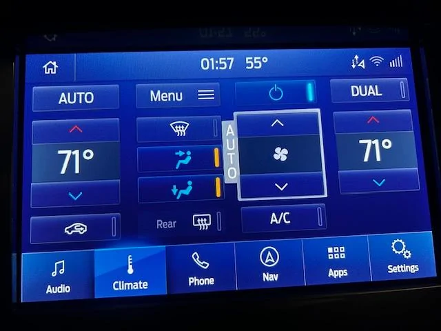
Being that the climate screen would be too cluttered by adding more buttons here they give you the option of Bi-Level Air by:
1. Floor / Panel = With FLOOR selected, you can press the PANEL button, this will select Bi-Level air.
or Vice-Versa the buttons.
2. Floor / Defrost = With FLOOR selected, you can press the DEFROST button, this will select Bi-Level air or Vice-Versa the buttons
When in Bi-Level mode, you will see both selections highlighted.
The only air distribution mode you CANNOT select is Bi-Level - PANEL / DEFROST
Example: Pics For Reference
2 buttons will be highlighted in (Bi-Level) Mode

Auto Control:
Auto Control and Primary Venting (Mode Position)
In AC or Max AC - Primary Output = Panel Vents
In Heat Mode - The Primary Output = Floor Vents (Heat Rises), the system will however adjust vent (mode) output depending on outside temperature and selected temperature.
I believe that the deciding factor is - If the Cabin Temp can be (COOLED) lower that the Outside Temp, then it will automatically switch between AC and Heat.
So, this would be somewhere NEAR 60 Deg (Outside Temp)
Ref Pic for Demister Vents (Location)
Let's look at the Temperature Sensors:
We have 6 Total Temperature Sensors in the HVAC System.
1. The Ambient Temp Sensor - This sensor reads the OAT (Outside Air Temp) and uses this to display on the Sync Screen, it also is an input to the system in Auto Mode - It factors this input and the Humidity Temp sensor input to determine how to control the system (Temp Doors) and (Mode Doors)
OAT + Cabin Temp - (Compares Both)
It is also used as the Primary input parameter for the AC Compressor Clutch (If above 32 deg) it will allow engagement.
If below 32 Deg - It disables the AC Compressor Clutch
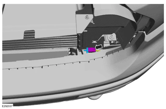
Ambient Temp Sensor (OAT) - Location (Front Grille Area)
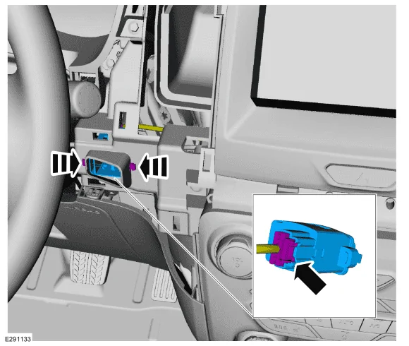
2. Temp / Humidity Sensor - This is the feedback sensor, and it reads actual cabin temp and humidity level of the cabin.
It is mounted by the Ignition Switch, as airflow is pulled across it (via a small electric fan) it is sampling cabin air temp and humidity.
From what you have selected on the Sync Screen let's say 72 Deg - In Dual Auto
The location of the Temp / Humidity sensor is on the driver's side.
The system is designed to maintain the selected cabin temp, now in Auto mode it is attempting to get the overall cabin temp (Mixed) to 72 Deg as fast as possible.
So, this will explain why the Driver's Side and Passenger Side - (Felt) temps may be different. (say in Heat mode)
It is balancing the cabin air temp.
Due to the many complaints about the Passenger Side (Feels Hotter) then the Driver's Side
This is what is happening.
The Passenger Temp door is commanded open a little farther to allow more heat into the passenger floor, you should note a rough (5 Deg) difference between Dr and Pass)
The reason for this is it is pushing hotter air into the passenger floor that will push to the driver's side and mix together then and when the system determines that the cabin temperature is able to maintain 72 Deg (Equally) then the Passenger Temp door closes some to equal the driver's temperature.
Now (IF) you select different temps between the Dr and Pass, then the Temp Doors will adjust accordingly open or closed to maintain the desired temperature split. (by controlling the amount, the Temp Door is opened or closed)
The Humidity Side of the Sensor - Controls the Air Inlet Door Actuator (Aka) Recirculation Door
If it senses high humidity, it will auto open the Recirc Door (If you are in Recirculation Mode)
The recirculation door operates as described above in the control section.
There is another sensor that can play a part in the automatic control of the Air Inlet Door and that is the Sunload Sensor (Below)
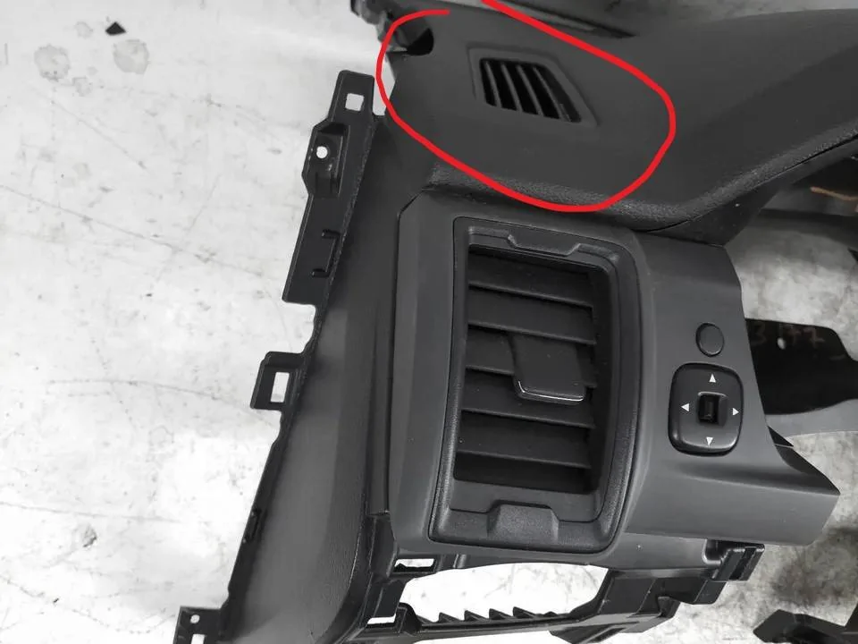
Temp / Humidity Sensor - Location
You will see a small vent on the dash at this location - Inlet for the sensor

3. Sunload Sensor:
This sensor performs double duty.
In the HVAC system, it measures the Sunlight intensity such as direct sunlight and calculates that when in direct sunlight the cabin temperature will be hotter than the actual outside temperature.
The sunload sensor supplies information to the FCIM indicating the intensity of the sun on the vehicle. The FCIM compensates high sun load with higher blower and reduced discharge temperatures. (so places the system in MAX AC, and drives the temp to full cold and blower speed to high (Automatically)
In the Dual Automatic System, during hot weather, it will automatically set the system in:
--MAX AC - Mode the system is using the Sunload Sensor as an input and it (Closes) the Recirculation Door, this is how the Sunload Sensor ties into the Temp Humidity Sensor which is the main sensor that controls the Air Inlet (Recirculation) Door, the Sunload Sensor is a (Seconday-Input) for control of the door.
The other job of the Sunload Sensor - Not Related to the HVAC, it is controlling the Auto Headlamps (On or Off)
Sunload Sensor Location (On the Dssh)
4. Driver's Foot and Panel Vent Air Discharge - Temperature Sensors (2ea)
These are the only (Output) temperature sensors in the system.
The purpose of these sensors is to measure the actual output temperature that is being generated (derived) from your selected temp, so in other words it is measuring the temperature of the air flowing past the Temp Door's
The system uses these Temp Inputs along with the Temp Humidity Sensor - To Control the system.
Discharge Temp is controlled by the amount the temp doors are open and the feedback is the Temp/Humidity sensor.
So, you can have an output temp as high as 160 deg. or so to get the cabin air (Mixed) and then the mixed air is picked up at the Temp/Humidity Sensor
The reason there is NOT sensors installed on the Passenger Side, is due to the fact that there is no need for it, as described above within the Airflow Section
The Panel and Foot air discharge temp will be the same in the HVAC (Blend / Mix) enclosed section.
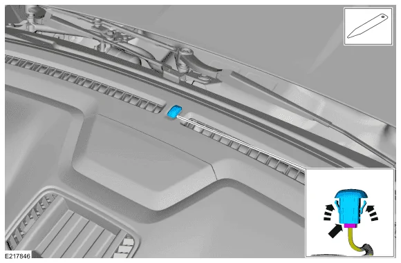
Drivers Footwell - Air Discharge Temp Sensor - Location
Just above the Brake Pedal
Driver's Panel Vent - Air Discharge Temp Sensor Location

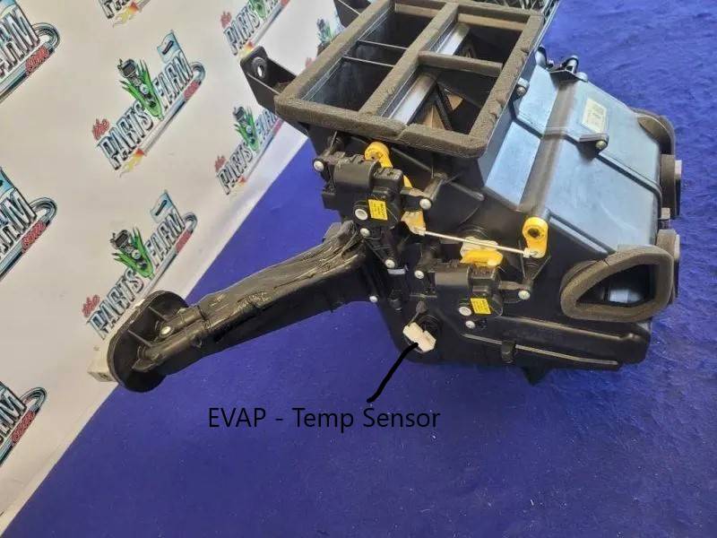
5. Evap Core Temp Sensor:
The purpose of the EVAP Temp Sensor is to monitor the Temp at the EVAP Core, to protect it from freezing over, at the EVAP core you have moisture from the Cabin Air and Outside Air around the EVAP core, when in AC Mode if the sensor reads below 33.8 deg, it will turn off the AC Compressor for a short period to allow the EVAP Core to warm up.
If you have a clogged condensate drain the HVAC box holds the water droplets coming off of the EVAP Core and this will produce an icing scenario at the EVAP Core, the Temp Sensor shuts off the AC Compressor and thus creates (2) complaints.
1. Low Airflow - Airflow is blocked by the iced over EVAP Core
2. Litte or No AC - The EVAP core is frozen over and airflow is blocked and cannot provide the COLD airflow as designed.
It has also shut off the AC Compressor
3. A dirty Cabin Filter- also can cause this type of complaint
Evap Temp Sensor - Location

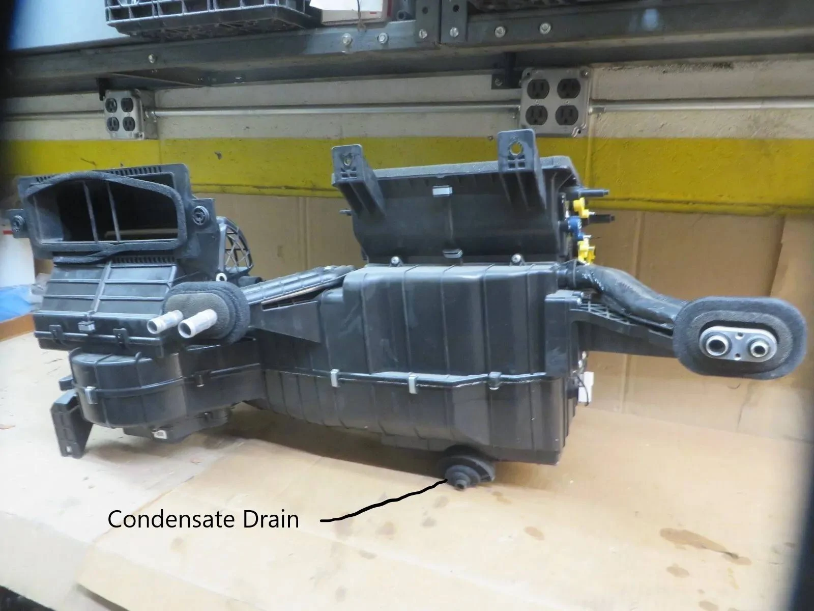
Condensate Drain - Location
Now due to the location of where this exits the firewall, it is near impossible to see from the engine bay.
The condensate drain drops just on top of the transmission bell housing and the top of the transmission holds most of what you normally see dropping on the ground when you park the truck.
But some owners have experienced blockage of the drain and the outcome of this is Condensate pooling up in the bottom of the HVAC Case and overflowing through the seams in the case and dumping it out on the floorboards. (MORE NOTED) in a turn
Troubleshooting Information:
Low Airflow Issues:
Possible Causes:
Dirty Cabin Filter or blocked Air Inlet (Leaves / Nests)
Evap Core Frozen (Iced Up) - During AC Operation - Summer Ops
Blower Motor - Housing (Squirrel Cage) - (filled with leaves / nests) or Blower Motor issue itself.
Mode Door Actuator, not moving to exact commanded position.
or an issue with the Bell Crank not moving the issued (mode) door correctly such as Foot Lever
This MAY or MAY NOT - generate the Popping / Clicking sound.
Piece of Debris - such as the foam that is used to seal the panels and doors and ducting connections, may have become dislodged and blocking the ducting airflow.
Piece of debris - that made it past the Cabin Air Filter - Leaves Etc and was sucked into the HVAC Box and now lodged and blocking the ducting.
Note: The Mode Door Actuator is moving 3ea sets of doors. (Defrost / Panel / Floor)
Low Airflow on (One Side) - Ex: Driver's Foot
Being that the Driver's Foor duct is located just above the Brake Pedal - It can be easily kicked with your foot.
It is possible that the duct was kicked, and it has become disconnected from the HVAC Housing or at its separation point (2-Piece) above the driver's footwell.
Temperature Issues:
Normal Operation is to provide a fully equal cabin temperature, (if both sides are set to the same temperature)
If we reflect back on the control section, this will allow to Passenger Side to possibly adjust the output temperature slightly higher (about 5 deg) than the Driver's Side. (Heat) (Opposite if AC - Slightly Lower)
The reason for this is to push a hotter / lower (Off-Balance) airflow to one side and get it to circulate within the cabin (Mixed)
The MIXED temperatures will help in getting the (Temp/Humdity) sensor to read overall cabin temperature.
The system is not (EXACT) but it is (APPROX)
Once the Temp/Humidity sensor - reads the expected temperature (Calculated-Programmed) it backs off the unequal temp delivery and then equals it out.
I am trying to explain what I viewed when testing with my scanner.
Basically, the Temp Humidity sensor can read a temperature of let's say 102 Deg, because that is the temperature it is reading from the driver's side airflow traveling up the dash (Heat Rises)
That does not mean that the Cabin is actually 102 Deg or the Passenger Side is anywhere near the selected temp.
Once the Cabin Temp is actually near the selected temp then the output temp will back down, so it will push hotter air in the beginning and then back off to maintain the desired selected temps.
It is all in the programming data of the FCIM and how the sensor operates.
One Note: On the Temp / Humidity Sensor - It has a small electric fan that draws air across it - to sample the cabin air (Temp/Humidity)
This sensor can become clogged with Dust/Dirt) and provide an invalid feedback reading. Thus, causing Temp Control Issues
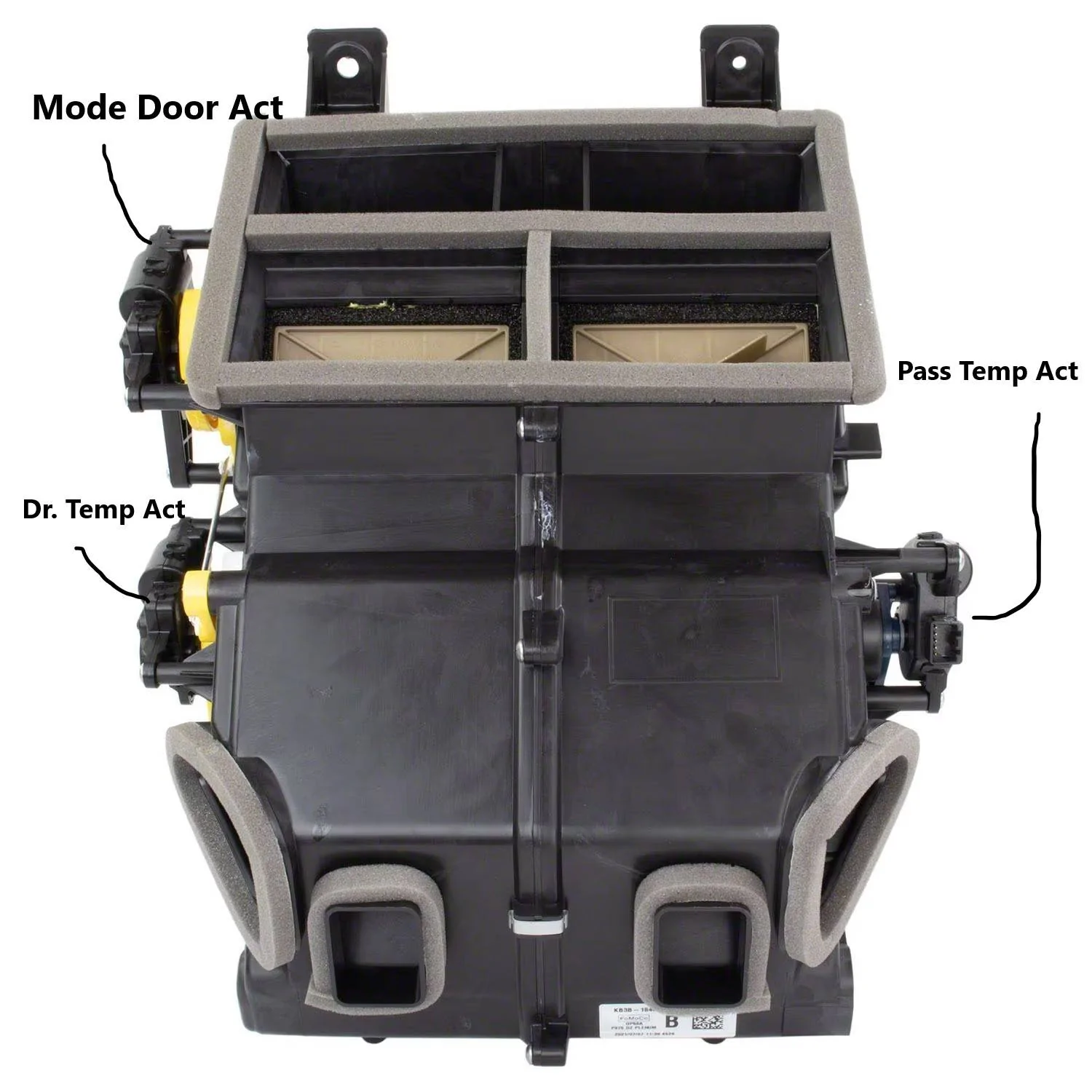
Temperature Issues (Aka Blend Doors)
If you have popping or clicking coming from under the dash when you are raising or lowering the temperature selection
Then it may be an issue with either Temp Door Actuator (Dr or Pass)
Note: Dual Climate has (2 Actuators) - Elect Manual (Single Zone) has (1 Actuator) that controls both side
The easiest way to check these actuators is to place the system in manual and drive each door full travel (full Cold to full Hot)
and note any popping and or clicking and feel the outlets for temperature rise or fall.
feel
The Best way is to use a scanner capable of reading the sensor position in addition to the feel and listen test.
As Seen Below:
for
Now this is where it is difficult to diagnose, as if you have a Popping or Clicking sound, we do not know if it is just the internal failure of the actuator (gears) jumping as it tries to find commanded position (internal feedback sensor) if it gets lost it will hunt and continue to attempt to drive into commanded position.
or
Is the Door Itself binding up and causing the actuator to bind and jump the gears.
As the actual Popping / Clicking sound is being generated by the actuator.
To isolate the issue, the actuator will need to be removed and then try to manually open and close the door by hand, however this may be a misleading troubleshooting step if the door binding up is temperature related (Intermittent)
EDIT From Original Post:
Added Temperature Issues Related to the Temperature Sensors:
For Complaints of NO HEAT at Floor but HAVE HEAT at the Panel or (Reversed Issues)
A Good example of a failed Temp Sensor would be using (Manual Mode) - Heat
If you select Panel - Good Cabin Control and Heat coming from panel vents
Floor - Weak or No Heat -Coming from Floor Vents
You can only see this with a scanner (Live Data) - an issue with one of these sensors should be throwing a code (Electrical) but if they are dirty, they will just give a false temp reading and think the discharged air is hotter than it really is - so it keeps the temperature door in a more closed position.
First: A Quick Review of Air Distribution
Panel:
Primary = Panel Vents (Strong Airflow) + Secondary = A VERY SMALL amount to the Defrost Vents Demist Vents and Floor Vents (Very Little Airflow)
The Recirculation button is enabled to allow you to press it to close the Air Inlet Door, but only for 5-Minutes, before it defaults back to open.
Floor:
Primary = Floor Vents (Strong Airflow) + Secondary = A VERY SMALL amount to the Defrost Vents Demist Vents and Floor Vents (Very Little Airflow)
The Recirculation button is enabled to allow you to press it to close the Air Inlet Door, but only for 5-Minutes, before it defaults back to open.
If you note the PRIMARY Airflow and view the Left Foot and Panel Discharge Temp Sensors with Scanner Live Data, you should see the Temperature Reading react according to selected Mode position.
In other words, if Floor is selected and Heat is selected, then the Floor Discharge Temp Reading should be reading a HIGHER temperature than the Panel. (Reversed for the Panel - Mode)
If you change the Mode to - Bi-Level (Floor/Panel)
You have about 75% of the air going to the Floor and 25% going to the Panel Vents.
If you watch the Temp sensors (Live Data) you should note that the Floor Discharge would be reading higher temps at first, then after the system has run for a while the Panel Temp should increase and match the Floor.
Basically, this little test would show an inaccurate temperature sensor, they may be off some but should be somewhat close to equal. You mainly want to see a reaction on the sensor's as you increase or decrease selected temperatures.
Edit: 11/18/24
I noted that the system has the capability to provide separate output temps to the defroster vents - so if the driver's and or passenger side temp door actuator is stuck cold you will only get heat on one side of the window for defrost.
I tested this by splitting the temps (LO & HI) and selecting defrost, to simulate a failed actuator.
The Mode Door Actuator- Can be replaced - But the Steering Colum, has to be dropped out of the way to replace it.
The Service Manuals do not even cover this actuator replacement and it is buried so dropping the steering column out of the way should give you access to it.
The Drivers Temp Door Actuator Can Be Replaced - But (per the service manual) The steering collum has to be dropped out of the way to replace it.
However, with a little finesse and patience and drilling an access hole to get one of the mounting screws it can be done without dropping the steering collum.
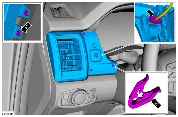
The Passenger Side Temp Door Actuator can be Replaced by Removing the Glove Box. (Moderate Access)
The Air Inlet Door (Recirculation) - Actuator can be Replaced by removing the Glove Box (Easy Access)
To replace the Doors themselves or the Heater Core or Evap Core:
The entire HVAC Assembly requires removal, this requires the whole dash console to be removed to get access.
To replace the Cabin Air Filter - Remove the Glove Box - Easy Access
To replace the Blower Motor - Easy Access - From the Passenger Floorboard
Let's Look at Scan Data (Live Data-PIDS) Related to the Climate Control System
Using my Autel 906TS - Scanner, most High End (Bi-Directional) Scanners have these PID's available.
I have not checked the Current Forscan Release, but as of yet I do not think Forscan can show these.
This shows Live Data of the FCIM (Front Control Interface Module)
This is where the Climate Control PID's are located.

This is just Overflow PID's related to the HVAC (The 2 unchecked) PID's at the bottom of the screen.
Showing the Cabin Temp Sensor Fan - On (Running) and the EVAP Core (Temp Reading)
Notes: For T/Shooting the system
In Manual Mode- you can select each position and they should match the readings below.
In Manual Mode - you can select Temperature up and down and watch the percentage raise or lower, you are looking for the percentage to increase or decrease without glitches or popping and clicking.
The most important is looking for FULL TRAVEL - 0-100%
Air Inlet Door Position:
The Air Inlet Door has 3 Operating positions.
Open - 100% - stays in this position the majority of the time.
Partially Open - 48% to 52% (uses this position at certain times) dependent on temp and humidity.
Closed / Recirculation (ON) - 0% - Closes when the Recirculation Button is selected but after a programmed (5-Minutes) it opens back up to 100%
In Max AC - It Closes 0%
With Truck Off - The Air Inlet Door Moves to 48% - (Partially Open) - (For Air Circulation - Ventilation In the HVAC-EVAP Core)
With System Turned Off (Truck Running) - The Air Inlet Door moves to 0% (Closed)
Note: Even when Closed (0%) the door is still about 10% open - this is to allow some fresh air into the Cab
T/Shoot Note: If you are hearing a Popping / Clicking sound at truck shut off and power up, and it is coming from the Passenger side, this MAY be the Air Inlet Door Actuator. (Located behind the Glove Box)
Mode Door Position: (Normal Readings as Follows)
Panel = 0%
Blend - Floor/Panel = 25%
Floor = 50%
Blend - Floor/Defrost = 75%
Defrost = 100%
With Truck Shut Off - Mode Door Moves to 25% - Panel/Floor (For Air Circulation - Ventilation In the HVAC-EVAP Core)
T/Shoot Note: If you are hearing a Popping / Clicking sound at truck shut off and power up, and it is coming from the Driver's side, this MAY be the Mode Door Actuator.
Left Blend Door Position:
This is the position of the Driver's Temperature Door
Hi (Heat) = 0%
Lo (Cold) = 100%
0% = Full Open
100% = Full Closed
Right Blend Door Position:
This is the position of the Passenger Temp Door.
Note: If you have Electronic Manual Control (Single Zone) you will only have (1) actuator controlling both the Dr & Pass Sides
and you will only see (Right Blend Door Position) you will not see the Left.
Hi (Heat) = 0%
Lo (Cold) = 100%
0% = Full Open
100% = Full Closed
With Truck Off - The Temp Doors (Blend) stay in place (current Position) and do not move
T/Shoot Note:
Starting with (LO) Temp selection - Slowly increase the Temp upwards and watch the Position Indication, ensure it follows without any glitch or jumpy readings and without any popping or clicking. (From 0% to 100%)
Repeat the test in the other direction. (From 100% to 0%)
If Popping or Clicking sound is heard, this may be the actuator itself or the door is binding.
Left Discharge Panel Temp:
The is the discharge air temp as measured in the Driver's (Left-Panel Vent)
Left Discharge Floor Temp:
This is the discharge air temp as measured in the Driver's Foot Vent
Depending on what mode you have selected - Floor / Panel / Blend - Temp Readings will vary, but for testing.
T/Shoot Note: If you are seeing an odd reading - Try removing and cleaning the sensor it may be dirty.
Heat:
In Manual Mode - Drive the Temp (HI) and you should see around 180 Deg in the Floor and around 165 Deg in the Panel with the engine at operating temp.
AC:
In Manual Mode - Drive the Temp (LO) and you should see a low Panel temperature reading, the actual reading will vary due to the ambient temp and humidity.
Some basic temp outputs for Ref:
70 Deg Day - Output Temp 35-40 Deg
80 Deg Day - Output Temp 45-50 Deg
100 Deg Day - Output Temp 55-60 Deg
The basic average is 35 to 40 Deg lower than the Ambient (Outside Temp)
External Amb Temp - Should match OAT Temp, using your phone etc, this is the temp displayed on the Sync Screen
Note: If the truck is sitting in the hot sun, it may take a few minutes of driving to get an accurate temperature reading.
Internal Amb Temp - This is the Temp/Humidity Sensor, this reading will vary and dependent upon the selected temp and the discharge temperatures from the panel and floor temp sensors.
Once the Cabin has reached a balanced temperature say 72 Deg, the sensor will read actual cabin temp and humidity.
T/Shoot Note: If you are seeing an odd reading - Try removing and cleaning the sensor it may be dirty.
Relative Humidity: Ties into the above, except this is the Input that controls the Air Inlet Door (Auto-Opens) if you have Recirculation Mode (Selected)
One Final Note:
The Temperature Control of the system wiring is a complex 5-Volt Reference system, and it is monitored by the FCIM so it can open or close the Air Inlet Door (Temp & Humidity) Monitoring.
and also control the system in (Automatic) Mode
The 5-Volt Reference wiring circuit entwines all the temperature sensors and door actuators on
the same circuit.
This allows the system to automatically move a door and the rest of the circuit knows exactly what position it moved to.
The door actuators are a 5-wire circuit.
3-Wires - 5-Volt Ref -V Ref Return - and Signal Wire (to move the door) (Feedback)
2-Wires - Are the Bi-Directional Power / Ground for the actuator motor
Depending on the direction the motor is commanded to move CW / CCW, is to which of the 2 wires are power or ground.
The command signal to move the door comes from the Feedback signal wire.
Since I do not have a spare HVAC Unit laying around, I have to do this with various online pics I found.
This is a Lengthy but Informative Thread:
AIR INLET:
Let's start with the Air Inlet Door
This is mounted just behind the Glovebox just above the cabin filter.
This door is an annoying design for some, and it also allows an easy point of entry for mice into the cab.
NOTE: Even when in Recirculation Mode, the door is NEVER 100 % Closed, it is designed to remain 10% OPEN even when it is closed.
The system is designed to operate mostly with the Door Opened to allow maximum outside air to be introduced into the cab, even with the system off you still have outside fresh air entering the cab through the open vents in the pic.
Note: When the HVAC is OFF - You do not have any airflow from the cab vents, but you do have - Fresh Air Intake coming into the cab from the Recirculation Air -(Open) vents - since the Air Inlet Door closes when off, since the Blower Motor is not running to suck this air into the HVAC, it just pushes it out of this opening.
and uses this as Fresh Air (Intake) and the air Exhaust out of the (Rear Cab - Exhaust Vents)
Note: HVAC Off = System Turned Off
The Air Inlet Door Moves to Partially Open - When the Truck is turned off.
The issue with the design of it not going 100 % closed, it will always remain at least 10 % open (in recirculation mode) is that the design of the air inlet being so large that any (skunk smell, smelly exhaust or SMOKE from Wildfires can easily be sucked into the cab.
Even if you place the system in recirculation mode to lower the amount of Outside Air (Input) the system has an internal Timer that only allows the door to be in recirculation mode for (5-Minutes) then it automatically opens back up.
While I cannot state how this is annoying for SMOKE areas of the country, I have noticed that this truck will inhale every obscure smell it gets driven through.
Much GREATER than any vehicle I have ever owned.
When you turn the truck off, this door powers to the partially open position - reason to vent the HVAC Box (mainly the Evap Core) to eliminate musty stale odors from the EVAP core and to assist in drying and or evaporating any moisture in the Condensate Drain and Evap core area.
The issue with this (needed) design is the size of the vent openings and also the engineering design leaving out an important need and that is a screen on the outside inlet air end.
Mice can find their way down under the plastic cowling (below the windshield) and crawl into the inner (metal cowling) and then enter this inlet port and down on top of the Cabin Air Filter and then able to fit through the vent openings as viewed in the pic.
They now have full access to the cab and the tasty dash wiring.
I cover more details on how and when this door operates later.
Edit: Added Info and Pic
Pic Showing how the door moves to partially open with truck shut off.
Note the opening and entry point for mice.
This is the reason to add a screen under the cowl, to block this access off for mice.
To understand operation of the door:
Rotates CW - Recirculation (ON) - Closing the Outside Air but does not actually fully close 100% it only closes about 90%, leaving roughly about 10% of an opening for Outside Air to enter the cab.
Rotates CCW - Recirculation (OFF)
If you remove the Plastic Cowling under the Windshield, you will see this opening. This is the inlet to for the Outside Air into the HVAC Box. (Passenger Side)
You can cover this opening with a screen (I used Drywall Sanding Screen) 120 Grit.
This prevents mice and debris entry into the Cab.
This also helps slow down the Air Intake by providing (SOME) blockage but still allows airflow. Lessens the Fowl Odors be sucked in so quickly.
This has no effect on the Blower Motor - Operation.
Pic showing Rear Cab - Exhaust Vents
AIR DISTRUBUTION:
To help visualize how the system operates let's take a look at the air distribution.
We have (1) Mode Door Actuator that controls (Moves) a Plastic Bell Crank (Yellow-Plastic Piece)
This moves 3 sets of Doors into position to distribute the selected airflow.
The visible doors in this pic show the Panel Air Doors
Note: For those that have issues with Foam pieces being blown out of the ducts / vents, if you look closely, you can see Foam around the Panel Vent Doors
There is Foam around the various doors and ducting to aid in sealing the system for airflow leaks.
Here is a view from a removed Dash Console
Now this pic shows the layout of the door levers that are driven by the yellow bell crank.
Note: The Lever I have labeled Floor is just the Driving lever for the Floor Follower - The Floor Follower is the Lever that is actually moving the Floor & Under Seat Doors.
Here is a pic of the Bell Crank that is driven (moved) by the Mode Door Actuator
Note: I cannot find a pic of the actual bell crank that is installed in this location, but this gives a general idea on how they connect and move in unison as the actuator rotates.

Pic Showing - Panel Airflow (Example) of how the doors move to close off the panel air.
Defrost Door - Driven by the Blue Lever
Here is a pic of the Floor Door, you can see it in the vent ports partially open position.
The Cutout at the bottom of the Unit is where the Heater Core Mounts
Here is a pic of the Floor Vent Door (Closed Position - No Airflow)
So, if you are in manual mode with Floor Selected, this will be open and if you are having weak airflow to the driver's floor duct above your foot then it is possible that the ductwork was kicked off and the air is coming out of this port instead of at the end of the duct above your foot.
Note: The Yellow lever just slightly above the outlet port, as the lever driven by the actuator cam rotates (CCW) the door is raised (Opened) to allow airflow to the Floor and Undereat Floor Vents
Basic Airflow to the Bottom of the Unit, then controlled by the various doors.
Note: The Location of the Heater Core
Picture this housing fully enclosed as it is mounted on the main unit.
There is constant airflow across the EVAP and Heater Core (at all times)
When MAX AC is selected the Heater Core is blocked, so you are bringing in outside air and blowing it across the cold EVAP Core.
The Temperature Doors automatically move to Full Cold (LO) and fully close (thus blocking heater core) airflow from entering the ductwork.
When AC is selected the airflow around the Heater Core is based on what you have (Temp Selected)
This uses both (Mixed/Blended) Airflow from the EVAP (Cold) and Heater Core (Heat) to get the desired output Temp selected.
When Heat is selected (The AC Compressor is OFF), so you will not have (Cold) airflow from the EVAP Core, and you will have only outside air blowing across the EVAP Core and Heater Core (Hot)
The Temperature Output depends on what you have selected, the Temperature Doors (Amount Opened) will dictate the amount of heat coming from the vents.
The Higher (Selected Temp) the greater the Temp Door is opened to get the heat from the Heater Core
Note: In Defrost Mode - If above 32 Deg F, the AC Compressor will operate to help in Defogging via removing moisture.
32 Deg F and below the AC Compressor - will NOT operate.
In Max Defrost Mode - The Temp is automatically selected to Full Hot (HI) so the Temperature Doors move to fully open position, allowing maximum heat to be pulled from the heater core.
Here we can see the Drivers & Passengers Temp Doors (Aka Blend Doors)
Dual Climate will have (2ea) Doors - With Individual Control
This pic shows (Electronic Manual Control) Single Zone
So Automatic (Dual Zone) will have 2 Temp Door Actuators mounted on each side (as depicted)
Single Zone - Has (1) Actuator mounted on the Pass Side and controls both doors via a Bell Crank driving a lever (similar to the blue lever pictured)
The White Lever off of the Passenger Single Zone actuator moves the Driver's Temp Door
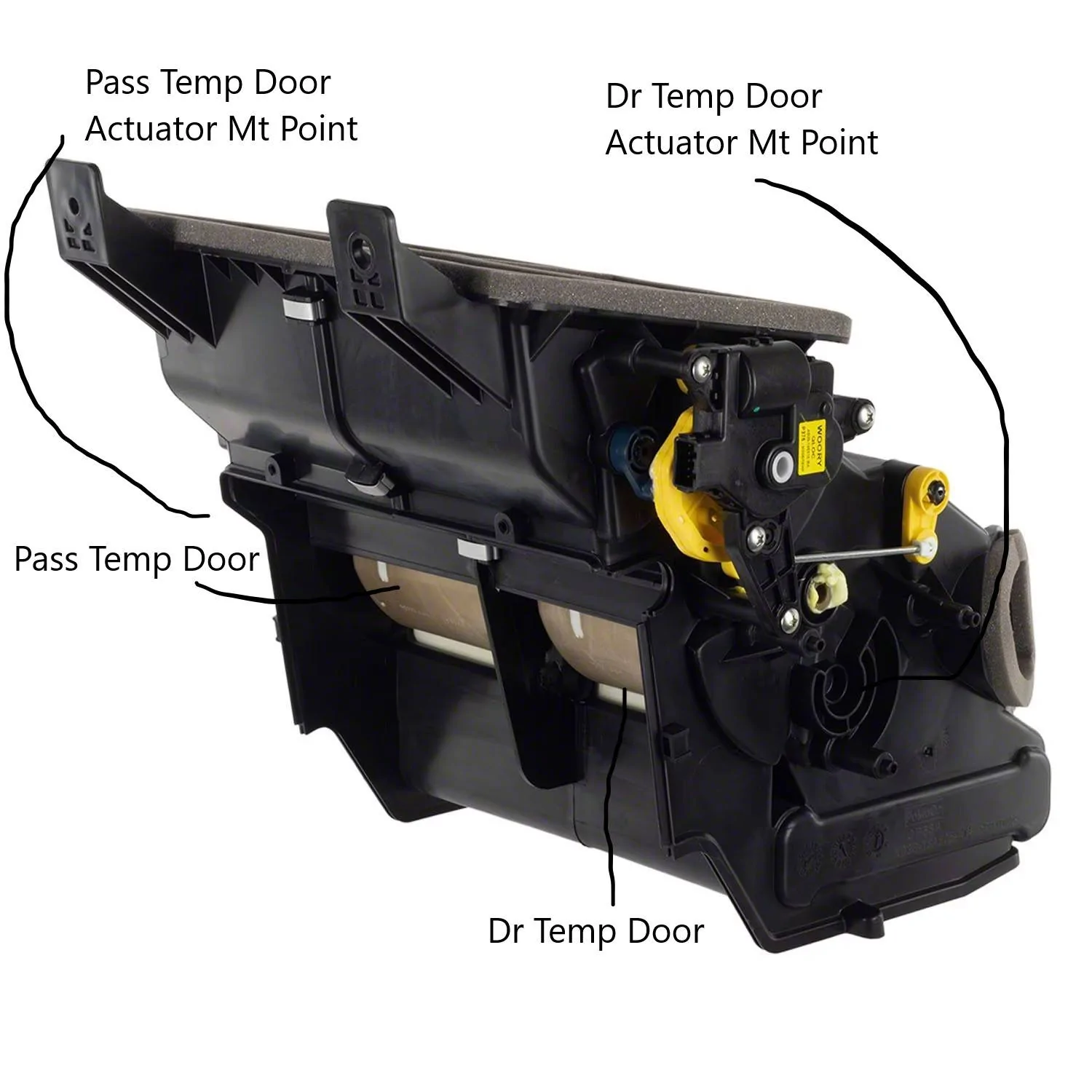
Electronic Manual Control (Single Zone)
Example of Dual Automatic Control
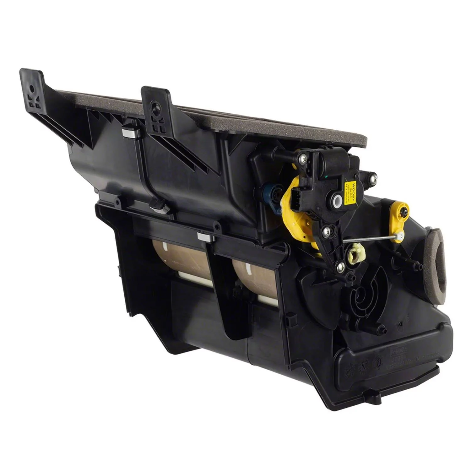
This shows where the Evaporator Core and the Heater Core, Mount to the HVAC Unit
This is how the Temp is regulated between the Cold and Heat
EVAP Core mounts to the Vertical
Heater Core mounts to the Bottom
If temps are not high enough for AC, then this would just be blended air coming from the Air Inlet and the amount the doors are open will dictate the amount of heat is allowed to be taken off of the heater core.
Airflow will travel around the heater core for heat.
or
Airflow will travel around the EVAP Core for AC
The (Open) amount of the Temp Doors adjusts the amount of Heated Air that is allowed into the duct work to the cabin.
Now let's reference the SSM for the Popping and Clicking sound, this video shows the Temp Door Actuator (Bell Crank) jumped.
This Video shows the (Electronic Manual) Single Zone version of the HVAC, the main part of the actuator shaft drives the opposite door (Driver's) and the lever that is bound up drives the (on-side) door (Passenger) - So this would be a case of the Passenger Side Temp, not being able to control complaint along with the Snapping and Popping sound.
2019 Ford Ranger Heat Not Working - YouTube
There appears to be separate SSM's that cover the same issue
Edited for more details.
Released Jan 23, 2023 (Most Current)
SSM 51313 2019-2020 Ranger - Climate Control Temperature Will Not Adjust With Clicking/Snapping Noise From The Dash - Built On Or Before 30-Jul-2020 Some 2019-2020 Ranger vehicles built on or before 30-Jul-2020 may experience poor and/or no temperature change when the temperature is adjusted in the climate control system. There may also be a clicking/snapping noise from behind the instrument panel. Diagnostic trouble code (DTC) B1082 and/or B1081 may also be retrieved from the front controls interface module (FCIM). This may be due to an issue with the blend door and its controls. To avoid repeat repairs, replace the air distribution housing/heater assembly (service base part# 18478). Refer to Workshop Manual (WSM), Section 412-00. Do not replace the evaporator core for this condition. The WSM has been updated to reflect this change. For claiming use causal part 18478 and use applicable labor operations in Section 11 of the Service Labor Time Standards (SLTS) Manual
This SSM only replaces the Heater Core Control Box Assembly
Note: The whole assembly has to be removed to replace this part, so this SSM 51313 only saves money on the cost of the part but adds some labor time to disassemble the assembly to replace this part of the HVAC unit.
Being that this is the problem area, this is the reason for the change in replacement procedures.
This Part: - Current Price for Auto Temp Control = $198.00
Released Oct 15, 2020
SSM 49264: 2019-2020 Ranger - Climate Control Temperature Will Not Adjust With Clicking/Snapping Noise From The Dash - Built On Or Before 30-Jul-2020 Some 2019-2020 Ranger vehicles built on or before 30-Jul-2020 may experience poor and/or no temperature change when the temperature is adjusted in the climate control system. There may also be a clicking/snapping noise from behind the instrument panel. Diagnostic trouble code (DTC) B1082 and/or B1081 may also be retrieved from the front controls interface module (FCIM). This may be due to an issue with the blend door and its controls. To avoid repeat repairs, it is recommended to replace the climate control housing assembly (service base part# 18478). Refer to Workshop Manual, Section 412-00. Vehicles: 2019-2020 Ranger P375N USA (FG) Symptom Code: 111000 BODY PANELS/UNIBODY B1081 B1082
This SSM Replaced the whole assembly.
This Part: - Current Price for Auto Temp Control = $1091.00
HVAC CONTROL:
Now we have covered the BASICS, Let's look at how we control it.
Let's look at Air Handling from the Control Head and where the air is distributed:
In the Selected Modes - This is where the air is distributed.
Note: Any air being delivered to the Floor Vents includes the Under Seat Vents
Note: When I state a VERY SMALL AMOUNT, it is just that, you can barely feel it, only a slight airflow is felt
Note: This airflow test was completed when in Manual Mode (Dual), Full Hot Temp Selected and Blower on High
Defrost:
Primary = Defrost Vents and Demist Vents (Strong Airflow) + Secondary = A Small Amount to the Floor Vents (Mild Airflow)
In Defrost Mode - The Air Inlet Door Opens and AC Compressor turns on (If above 32 Deg) via Ambient Temp Sensor (Input)
To remove humidity.
The Recirculation Button - Is DISABLED
Max Defrost:
The Blower Speed will automatically be commanded to High (Not Adjustable) and the Temp is automatically set to HI (Heat) and the Rear Window / Side Mirror Heat is automatically commanded ON.
The Air Inlet Door Opens and AC Compressor turns on (If above 32 Deg) via Ambient Temp Sensor (Input)
To remove humidity.
The Recirculation Button - Is DISABLED
AC:
The AC Button, can be selected and it will activate the AC Compressor clutch if above 32 Deg (Ambient - Outside Temp) and the Evap Core Temp is above 33.8 Deg.
Max AC:
The Air Inlet Door (Closes) - (Recirculation-Mode) - The Blower Motor speed is automatically commanded to HIGH, but can be manually adj to a lower setting and still remain in Max AC Mode. The Temperature is automatically set to full LO (Cold)
Panel:
Primary = Panel Vents (Strong Airflow) + Secondary = A VERY SMALL amount to the Defrost Vents Demist Vents and Floor Vents (Very Little Airflow)
The Recirculation button is enabled to allow you to press it to close the Air Inlet Door, but only for 5-Minutes, before it defaults back to open.
Floor:
Primary = Floor Vents (Strong Airflow) + Secondary = A VERY SMALL amount to the Defrost Vents Demist Vents and Floor Vents (Very Little Airflow)
The Recirculation button is enabled to allow you to press it to close the Air Inlet Door, but only for 5-Minutes, before it defaults back to open.
Bi-Level (Floor / Panel)
Primary = Approx 75% to the Floor Vents and Approx 25% to the Panel Vents + Secondary = A VERY SMALL amount to the Defrost Vents Demist Vents (Very Little)
The Recirculation button is enabled to allow you to press it to close the Air Inlet Door, but only for 5-Minutes, before it defaults back to open.
Bi-Level (Floor / Defrost)
Primary = Floor Vents, Defrost Vents and Demist Vents (Mild Equal Airflow) + Secondary = NONE
The Recirculation button is enabled to allow you to press it to close the Air Inlet Door, but only for 5-Minutes, before it defaults back to open.
EDIT From Original Post:
To fully understand how to get B-Level Airflow
Being that the climate screen would be too cluttered by adding more buttons here they give you the option of Bi-Level Air by:
1. Floor / Panel = With FLOOR selected, you can press the PANEL button, this will select Bi-Level air.
or Vice-Versa the buttons.
2. Floor / Defrost = With FLOOR selected, you can press the DEFROST button, this will select Bi-Level air or Vice-Versa the buttons
When in Bi-Level mode, you will see both selections highlighted.
The only air distribution mode you CANNOT select is Bi-Level - PANEL / DEFROST
Example: Pics For Reference
2 buttons will be highlighted in (Bi-Level) Mode
Auto Control:
Auto Control and Primary Venting (Mode Position)
In AC or Max AC - Primary Output = Panel Vents
In Heat Mode - The Primary Output = Floor Vents (Heat Rises), the system will however adjust vent (mode) output depending on outside temperature and selected temperature.
I believe that the deciding factor is - If the Cabin Temp can be (COOLED) lower that the Outside Temp, then it will automatically switch between AC and Heat.
So, this would be somewhere NEAR 60 Deg (Outside Temp)
Ref Pic for Demister Vents (Location)
Let's look at the Temperature Sensors:
We have 6 Total Temperature Sensors in the HVAC System.
1. The Ambient Temp Sensor - This sensor reads the OAT (Outside Air Temp) and uses this to display on the Sync Screen, it also is an input to the system in Auto Mode - It factors this input and the Humidity Temp sensor input to determine how to control the system (Temp Doors) and (Mode Doors)
OAT + Cabin Temp - (Compares Both)
It is also used as the Primary input parameter for the AC Compressor Clutch (If above 32 deg) it will allow engagement.
If below 32 Deg - It disables the AC Compressor Clutch
Ambient Temp Sensor (OAT) - Location (Front Grille Area)
2. Temp / Humidity Sensor - This is the feedback sensor, and it reads actual cabin temp and humidity level of the cabin.
It is mounted by the Ignition Switch, as airflow is pulled across it (via a small electric fan) it is sampling cabin air temp and humidity.
From what you have selected on the Sync Screen let's say 72 Deg - In Dual Auto
The location of the Temp / Humidity sensor is on the driver's side.
The system is designed to maintain the selected cabin temp, now in Auto mode it is attempting to get the overall cabin temp (Mixed) to 72 Deg as fast as possible.
So, this will explain why the Driver's Side and Passenger Side - (Felt) temps may be different. (say in Heat mode)
It is balancing the cabin air temp.
Due to the many complaints about the Passenger Side (Feels Hotter) then the Driver's Side
This is what is happening.
The Passenger Temp door is commanded open a little farther to allow more heat into the passenger floor, you should note a rough (5 Deg) difference between Dr and Pass)
The reason for this is it is pushing hotter air into the passenger floor that will push to the driver's side and mix together then and when the system determines that the cabin temperature is able to maintain 72 Deg (Equally) then the Passenger Temp door closes some to equal the driver's temperature.
Now (IF) you select different temps between the Dr and Pass, then the Temp Doors will adjust accordingly open or closed to maintain the desired temperature split. (by controlling the amount, the Temp Door is opened or closed)
The Humidity Side of the Sensor - Controls the Air Inlet Door Actuator (Aka) Recirculation Door
If it senses high humidity, it will auto open the Recirc Door (If you are in Recirculation Mode)
The recirculation door operates as described above in the control section.
There is another sensor that can play a part in the automatic control of the Air Inlet Door and that is the Sunload Sensor (Below)
Temp / Humidity Sensor - Location
You will see a small vent on the dash at this location - Inlet for the sensor
3. Sunload Sensor:
This sensor performs double duty.
In the HVAC system, it measures the Sunlight intensity such as direct sunlight and calculates that when in direct sunlight the cabin temperature will be hotter than the actual outside temperature.
The sunload sensor supplies information to the FCIM indicating the intensity of the sun on the vehicle. The FCIM compensates high sun load with higher blower and reduced discharge temperatures. (so places the system in MAX AC, and drives the temp to full cold and blower speed to high (Automatically)
In the Dual Automatic System, during hot weather, it will automatically set the system in:
--MAX AC - Mode the system is using the Sunload Sensor as an input and it (Closes) the Recirculation Door, this is how the Sunload Sensor ties into the Temp Humidity Sensor which is the main sensor that controls the Air Inlet (Recirculation) Door, the Sunload Sensor is a (Seconday-Input) for control of the door.
The other job of the Sunload Sensor - Not Related to the HVAC, it is controlling the Auto Headlamps (On or Off)
Sunload Sensor Location (On the Dssh)
4. Driver's Foot and Panel Vent Air Discharge - Temperature Sensors (2ea)
These are the only (Output) temperature sensors in the system.
The purpose of these sensors is to measure the actual output temperature that is being generated (derived) from your selected temp, so in other words it is measuring the temperature of the air flowing past the Temp Door's
The system uses these Temp Inputs along with the Temp Humidity Sensor - To Control the system.
Discharge Temp is controlled by the amount the temp doors are open and the feedback is the Temp/Humidity sensor.
So, you can have an output temp as high as 160 deg. or so to get the cabin air (Mixed) and then the mixed air is picked up at the Temp/Humidity Sensor
The reason there is NOT sensors installed on the Passenger Side, is due to the fact that there is no need for it, as described above within the Airflow Section
The Panel and Foot air discharge temp will be the same in the HVAC (Blend / Mix) enclosed section.
Drivers Footwell - Air Discharge Temp Sensor - Location
Just above the Brake Pedal
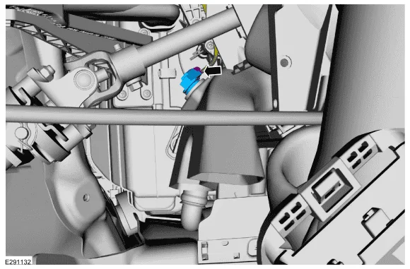
Driver's Panel Vent - Air Discharge Temp Sensor Location
5. Evap Core Temp Sensor:
The purpose of the EVAP Temp Sensor is to monitor the Temp at the EVAP Core, to protect it from freezing over, at the EVAP core you have moisture from the Cabin Air and Outside Air around the EVAP core, when in AC Mode if the sensor reads below 33.8 deg, it will turn off the AC Compressor for a short period to allow the EVAP Core to warm up.
If you have a clogged condensate drain the HVAC box holds the water droplets coming off of the EVAP Core and this will produce an icing scenario at the EVAP Core, the Temp Sensor shuts off the AC Compressor and thus creates (2) complaints.
1. Low Airflow - Airflow is blocked by the iced over EVAP Core
2. Litte or No AC - The EVAP core is frozen over and airflow is blocked and cannot provide the COLD airflow as designed.
It has also shut off the AC Compressor
3. A dirty Cabin Filter- also can cause this type of complaint
Evap Temp Sensor - Location
Condensate Drain - Location
Now due to the location of where this exits the firewall, it is near impossible to see from the engine bay.
The condensate drain drops just on top of the transmission bell housing and the top of the transmission holds most of what you normally see dropping on the ground when you park the truck.
But some owners have experienced blockage of the drain and the outcome of this is Condensate pooling up in the bottom of the HVAC Case and overflowing through the seams in the case and dumping it out on the floorboards. (MORE NOTED) in a turn
Troubleshooting Information:
Low Airflow Issues:
Possible Causes:
Dirty Cabin Filter or blocked Air Inlet (Leaves / Nests)
Evap Core Frozen (Iced Up) - During AC Operation - Summer Ops
Blower Motor - Housing (Squirrel Cage) - (filled with leaves / nests) or Blower Motor issue itself.
Mode Door Actuator, not moving to exact commanded position.
or an issue with the Bell Crank not moving the issued (mode) door correctly such as Foot Lever
This MAY or MAY NOT - generate the Popping / Clicking sound.
Piece of Debris - such as the foam that is used to seal the panels and doors and ducting connections, may have become dislodged and blocking the ducting airflow.
Piece of debris - that made it past the Cabin Air Filter - Leaves Etc and was sucked into the HVAC Box and now lodged and blocking the ducting.
Note: The Mode Door Actuator is moving 3ea sets of doors. (Defrost / Panel / Floor)
Low Airflow on (One Side) - Ex: Driver's Foot
Being that the Driver's Foor duct is located just above the Brake Pedal - It can be easily kicked with your foot.
It is possible that the duct was kicked, and it has become disconnected from the HVAC Housing or at its separation point (2-Piece) above the driver's footwell.
Temperature Issues:
Normal Operation is to provide a fully equal cabin temperature, (if both sides are set to the same temperature)
If we reflect back on the control section, this will allow to Passenger Side to possibly adjust the output temperature slightly higher (about 5 deg) than the Driver's Side. (Heat) (Opposite if AC - Slightly Lower)
The reason for this is to push a hotter / lower (Off-Balance) airflow to one side and get it to circulate within the cabin (Mixed)
The MIXED temperatures will help in getting the (Temp/Humdity) sensor to read overall cabin temperature.
The system is not (EXACT) but it is (APPROX)
Once the Temp/Humidity sensor - reads the expected temperature (Calculated-Programmed) it backs off the unequal temp delivery and then equals it out.
I am trying to explain what I viewed when testing with my scanner.
Basically, the Temp Humidity sensor can read a temperature of let's say 102 Deg, because that is the temperature it is reading from the driver's side airflow traveling up the dash (Heat Rises)
That does not mean that the Cabin is actually 102 Deg or the Passenger Side is anywhere near the selected temp.
Once the Cabin Temp is actually near the selected temp then the output temp will back down, so it will push hotter air in the beginning and then back off to maintain the desired selected temps.
It is all in the programming data of the FCIM and how the sensor operates.
One Note: On the Temp / Humidity Sensor - It has a small electric fan that draws air across it - to sample the cabin air (Temp/Humidity)
This sensor can become clogged with Dust/Dirt) and provide an invalid feedback reading. Thus, causing Temp Control Issues
Temperature Issues (Aka Blend Doors)
If you have popping or clicking coming from under the dash when you are raising or lowering the temperature selection
Then it may be an issue with either Temp Door Actuator (Dr or Pass)
Note: Dual Climate has (2 Actuators) - Elect Manual (Single Zone) has (1 Actuator) that controls both side
The easiest way to check these actuators is to place the system in manual and drive each door full travel (full Cold to full Hot)
and note any popping and or clicking and feel the outlets for temperature rise or fall.
feel
The Best way is to use a scanner capable of reading the sensor position in addition to the feel and listen test.
As Seen Below:
for
Now this is where it is difficult to diagnose, as if you have a Popping or Clicking sound, we do not know if it is just the internal failure of the actuator (gears) jumping as it tries to find commanded position (internal feedback sensor) if it gets lost it will hunt and continue to attempt to drive into commanded position.
or
Is the Door Itself binding up and causing the actuator to bind and jump the gears.
As the actual Popping / Clicking sound is being generated by the actuator.
To isolate the issue, the actuator will need to be removed and then try to manually open and close the door by hand, however this may be a misleading troubleshooting step if the door binding up is temperature related (Intermittent)
EDIT From Original Post:
Added Temperature Issues Related to the Temperature Sensors:
For Complaints of NO HEAT at Floor but HAVE HEAT at the Panel or (Reversed Issues)
A Good example of a failed Temp Sensor would be using (Manual Mode) - Heat
If you select Panel - Good Cabin Control and Heat coming from panel vents
Floor - Weak or No Heat -Coming from Floor Vents
You can only see this with a scanner (Live Data) - an issue with one of these sensors should be throwing a code (Electrical) but if they are dirty, they will just give a false temp reading and think the discharged air is hotter than it really is - so it keeps the temperature door in a more closed position.
First: A Quick Review of Air Distribution
Panel:
Primary = Panel Vents (Strong Airflow) + Secondary = A VERY SMALL amount to the Defrost Vents Demist Vents and Floor Vents (Very Little Airflow)
The Recirculation button is enabled to allow you to press it to close the Air Inlet Door, but only for 5-Minutes, before it defaults back to open.
Floor:
Primary = Floor Vents (Strong Airflow) + Secondary = A VERY SMALL amount to the Defrost Vents Demist Vents and Floor Vents (Very Little Airflow)
The Recirculation button is enabled to allow you to press it to close the Air Inlet Door, but only for 5-Minutes, before it defaults back to open.
If you note the PRIMARY Airflow and view the Left Foot and Panel Discharge Temp Sensors with Scanner Live Data, you should see the Temperature Reading react according to selected Mode position.
In other words, if Floor is selected and Heat is selected, then the Floor Discharge Temp Reading should be reading a HIGHER temperature than the Panel. (Reversed for the Panel - Mode)
If you change the Mode to - Bi-Level (Floor/Panel)
You have about 75% of the air going to the Floor and 25% going to the Panel Vents.
If you watch the Temp sensors (Live Data) you should note that the Floor Discharge would be reading higher temps at first, then after the system has run for a while the Panel Temp should increase and match the Floor.
Basically, this little test would show an inaccurate temperature sensor, they may be off some but should be somewhat close to equal. You mainly want to see a reaction on the sensor's as you increase or decrease selected temperatures.
Edit: 11/18/24
I noted that the system has the capability to provide separate output temps to the defroster vents - so if the driver's and or passenger side temp door actuator is stuck cold you will only get heat on one side of the window for defrost.
I tested this by splitting the temps (LO & HI) and selecting defrost, to simulate a failed actuator.
The Mode Door Actuator- Can be replaced - But the Steering Colum, has to be dropped out of the way to replace it.
The Service Manuals do not even cover this actuator replacement and it is buried so dropping the steering column out of the way should give you access to it.
The Drivers Temp Door Actuator Can Be Replaced - But (per the service manual) The steering collum has to be dropped out of the way to replace it.
However, with a little finesse and patience and drilling an access hole to get one of the mounting screws it can be done without dropping the steering collum.
The Passenger Side Temp Door Actuator can be Replaced by Removing the Glove Box. (Moderate Access)
The Air Inlet Door (Recirculation) - Actuator can be Replaced by removing the Glove Box (Easy Access)
To replace the Doors themselves or the Heater Core or Evap Core:
The entire HVAC Assembly requires removal, this requires the whole dash console to be removed to get access.
To replace the Cabin Air Filter - Remove the Glove Box - Easy Access
To replace the Blower Motor - Easy Access - From the Passenger Floorboard
Let's Look at Scan Data (Live Data-PIDS) Related to the Climate Control System
Using my Autel 906TS - Scanner, most High End (Bi-Directional) Scanners have these PID's available.
I have not checked the Current Forscan Release, but as of yet I do not think Forscan can show these.
This shows Live Data of the FCIM (Front Control Interface Module)
This is where the Climate Control PID's are located.
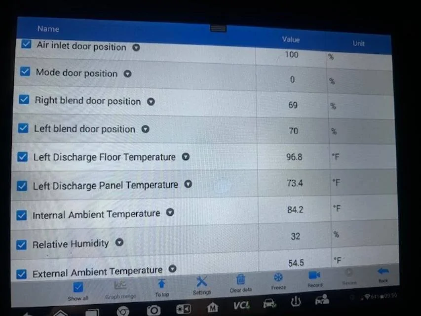
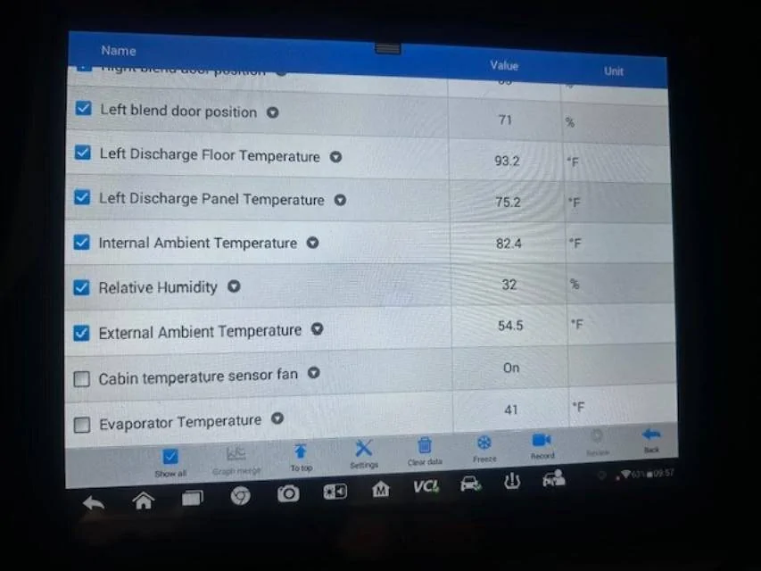
This is just Overflow PID's related to the HVAC (The 2 unchecked) PID's at the bottom of the screen.
Showing the Cabin Temp Sensor Fan - On (Running) and the EVAP Core (Temp Reading)
Notes: For T/Shooting the system
In Manual Mode- you can select each position and they should match the readings below.
In Manual Mode - you can select Temperature up and down and watch the percentage raise or lower, you are looking for the percentage to increase or decrease without glitches or popping and clicking.
The most important is looking for FULL TRAVEL - 0-100%
Air Inlet Door Position:
The Air Inlet Door has 3 Operating positions.
Open - 100% - stays in this position the majority of the time.
Partially Open - 48% to 52% (uses this position at certain times) dependent on temp and humidity.
Closed / Recirculation (ON) - 0% - Closes when the Recirculation Button is selected but after a programmed (5-Minutes) it opens back up to 100%
In Max AC - It Closes 0%
With Truck Off - The Air Inlet Door Moves to 48% - (Partially Open) - (For Air Circulation - Ventilation In the HVAC-EVAP Core)
With System Turned Off (Truck Running) - The Air Inlet Door moves to 0% (Closed)
Note: Even when Closed (0%) the door is still about 10% open - this is to allow some fresh air into the Cab
T/Shoot Note: If you are hearing a Popping / Clicking sound at truck shut off and power up, and it is coming from the Passenger side, this MAY be the Air Inlet Door Actuator. (Located behind the Glove Box)
Mode Door Position: (Normal Readings as Follows)
Panel = 0%
Blend - Floor/Panel = 25%
Floor = 50%
Blend - Floor/Defrost = 75%
Defrost = 100%
With Truck Shut Off - Mode Door Moves to 25% - Panel/Floor (For Air Circulation - Ventilation In the HVAC-EVAP Core)
T/Shoot Note: If you are hearing a Popping / Clicking sound at truck shut off and power up, and it is coming from the Driver's side, this MAY be the Mode Door Actuator.
Left Blend Door Position:
This is the position of the Driver's Temperature Door
Hi (Heat) = 0%
Lo (Cold) = 100%
0% = Full Open
100% = Full Closed
Right Blend Door Position:
This is the position of the Passenger Temp Door.
Note: If you have Electronic Manual Control (Single Zone) you will only have (1) actuator controlling both the Dr & Pass Sides
and you will only see (Right Blend Door Position) you will not see the Left.
Hi (Heat) = 0%
Lo (Cold) = 100%
0% = Full Open
100% = Full Closed
With Truck Off - The Temp Doors (Blend) stay in place (current Position) and do not move
T/Shoot Note:
Starting with (LO) Temp selection - Slowly increase the Temp upwards and watch the Position Indication, ensure it follows without any glitch or jumpy readings and without any popping or clicking. (From 0% to 100%)
Repeat the test in the other direction. (From 100% to 0%)
If Popping or Clicking sound is heard, this may be the actuator itself or the door is binding.
Left Discharge Panel Temp:
The is the discharge air temp as measured in the Driver's (Left-Panel Vent)
Left Discharge Floor Temp:
This is the discharge air temp as measured in the Driver's Foot Vent
Depending on what mode you have selected - Floor / Panel / Blend - Temp Readings will vary, but for testing.
T/Shoot Note: If you are seeing an odd reading - Try removing and cleaning the sensor it may be dirty.
Heat:
In Manual Mode - Drive the Temp (HI) and you should see around 180 Deg in the Floor and around 165 Deg in the Panel with the engine at operating temp.
AC:
In Manual Mode - Drive the Temp (LO) and you should see a low Panel temperature reading, the actual reading will vary due to the ambient temp and humidity.
Some basic temp outputs for Ref:
70 Deg Day - Output Temp 35-40 Deg
80 Deg Day - Output Temp 45-50 Deg
100 Deg Day - Output Temp 55-60 Deg
The basic average is 35 to 40 Deg lower than the Ambient (Outside Temp)
External Amb Temp - Should match OAT Temp, using your phone etc, this is the temp displayed on the Sync Screen
Note: If the truck is sitting in the hot sun, it may take a few minutes of driving to get an accurate temperature reading.
Internal Amb Temp - This is the Temp/Humidity Sensor, this reading will vary and dependent upon the selected temp and the discharge temperatures from the panel and floor temp sensors.
Once the Cabin has reached a balanced temperature say 72 Deg, the sensor will read actual cabin temp and humidity.
T/Shoot Note: If you are seeing an odd reading - Try removing and cleaning the sensor it may be dirty.
Relative Humidity: Ties into the above, except this is the Input that controls the Air Inlet Door (Auto-Opens) if you have Recirculation Mode (Selected)
One Final Note:
The Temperature Control of the system wiring is a complex 5-Volt Reference system, and it is monitored by the FCIM so it can open or close the Air Inlet Door (Temp & Humidity) Monitoring.
and also control the system in (Automatic) Mode
The 5-Volt Reference wiring circuit entwines all the temperature sensors and door actuators on
the same circuit.
This allows the system to automatically move a door and the rest of the circuit knows exactly what position it moved to.
The door actuators are a 5-wire circuit.
3-Wires - 5-Volt Ref -V Ref Return - and Signal Wire (to move the door) (Feedback)
2-Wires - Are the Bi-Directional Power / Ground for the actuator motor
Depending on the direction the motor is commanded to move CW / CCW, is to which of the 2 wires are power or ground.
The command signal to move the door comes from the Feedback signal wire.
Sponsored
Last edited:

") All your info has been great.
All your info has been great.