RangerLife
Member
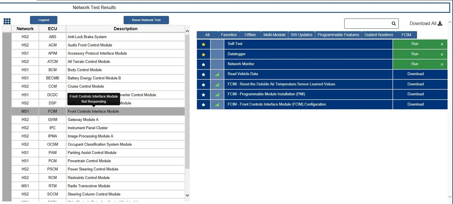
Finally got it back and installed; here are the codes it is throwing in general:Once you get it all back and installed, we need to check.
1. Power & Ground at the FCIM connector
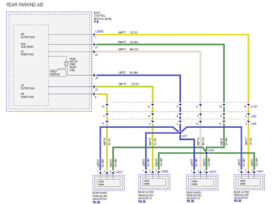
2. The Can Bus Wiring
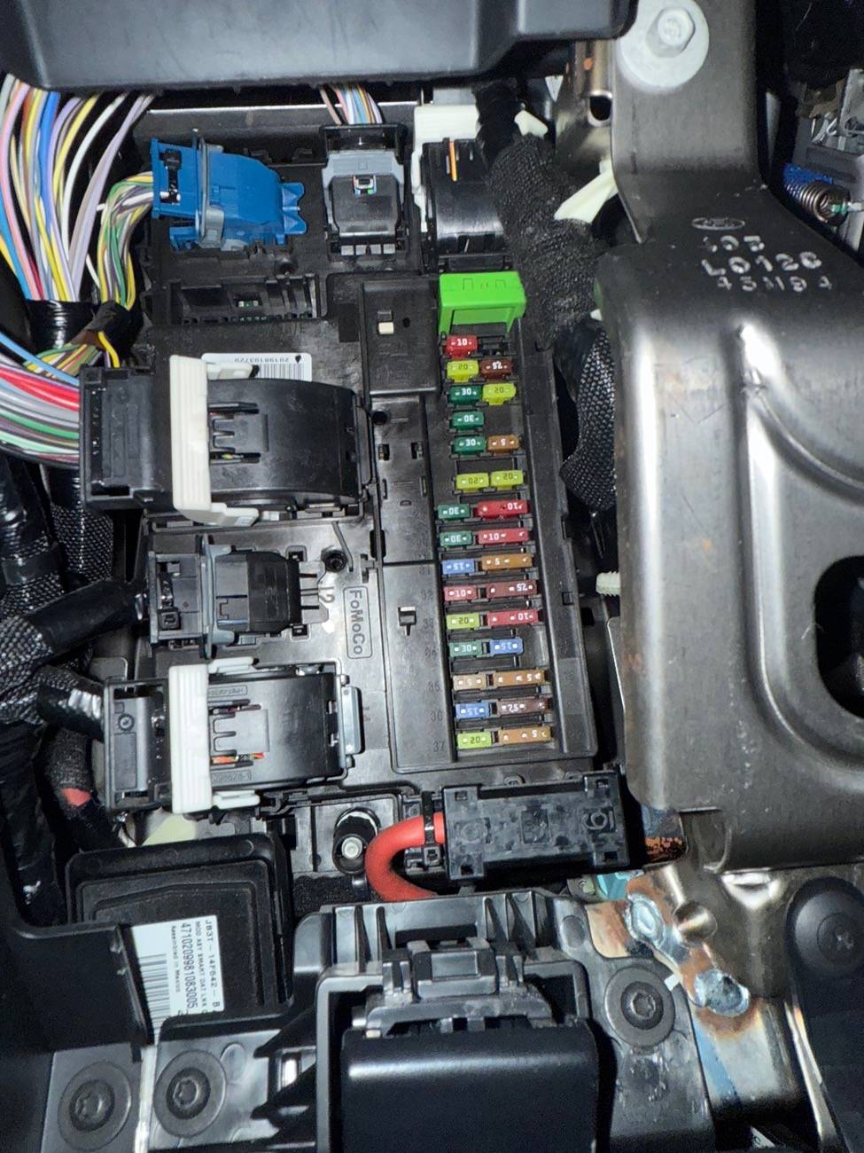
There is (1) more connector C422 we can try to (Clean & Reseat)
and one more possible source (avenue) to get the FCIM to power.
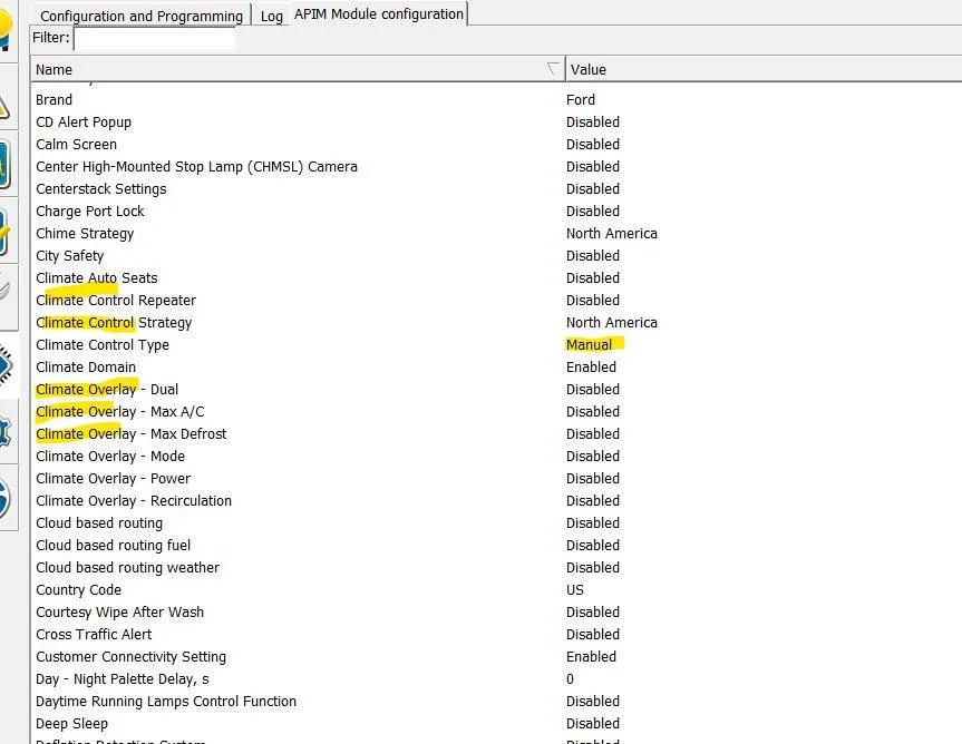
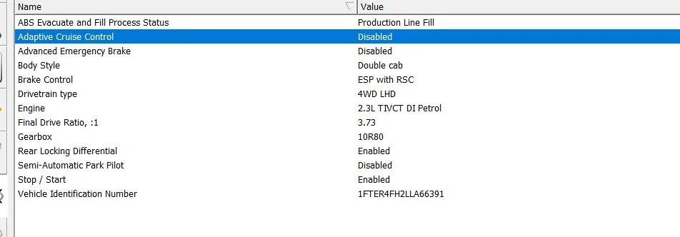
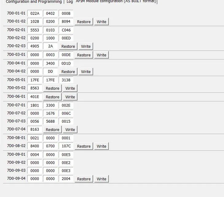
With the APIM being programmed by 4D Tech and it is needing the As-Built files to match the added FCIM - it is possible Ford wiped that programming back to stock and MAY be the reason for the FCIM not powering as the APIM may be set incorrectly - Note there is not a VIN# in the APIM but the settings may have been changed.
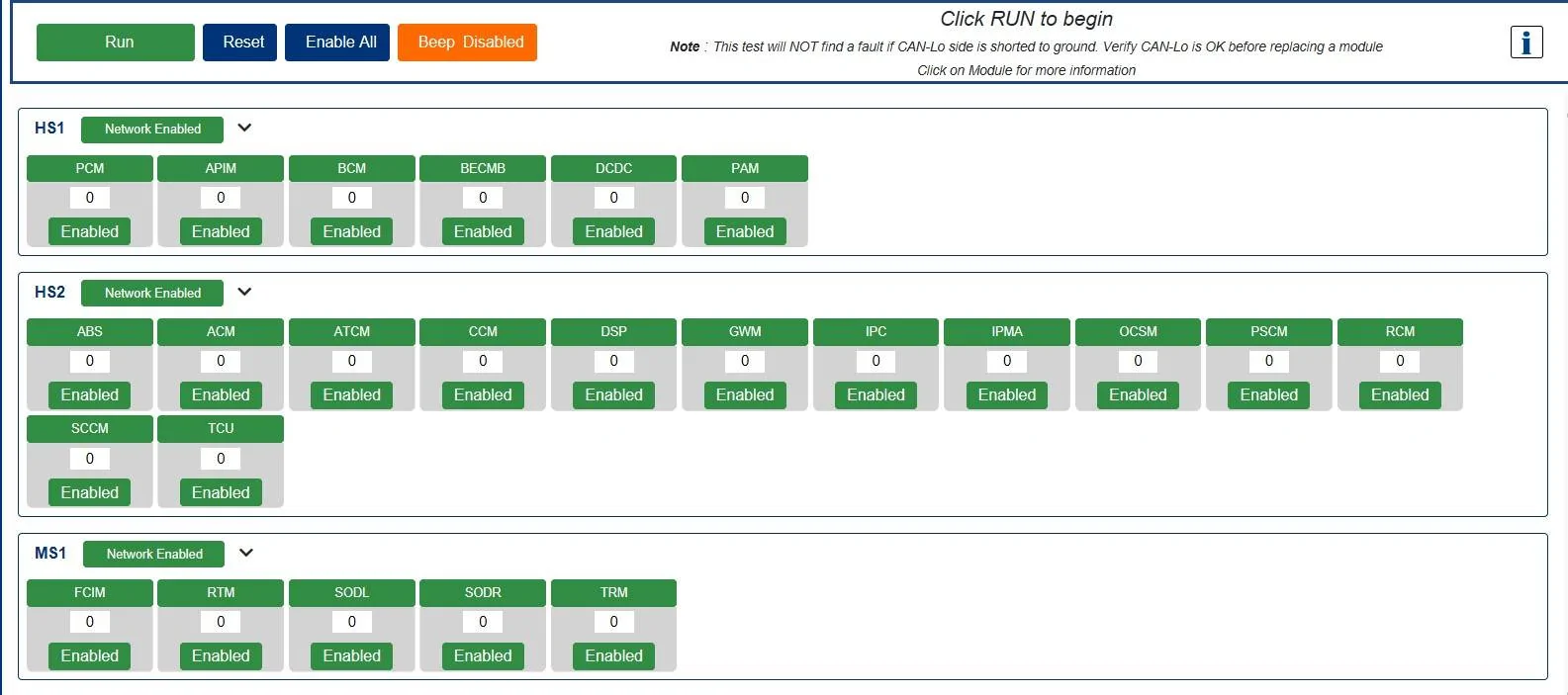
Since you are able to communicate to the APIM.
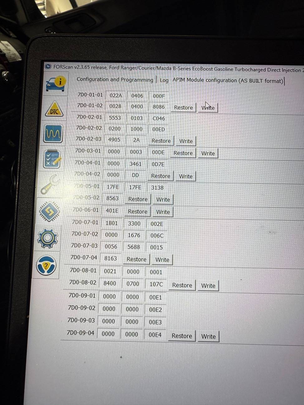
Post the APIM As-Built data you have so I can see if anything stands out as incorrect.
I am thinking outside the box here as a possible issue.
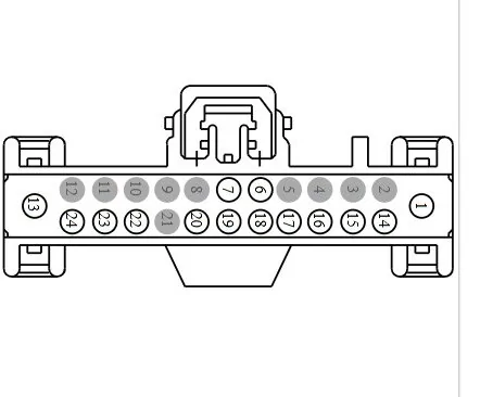
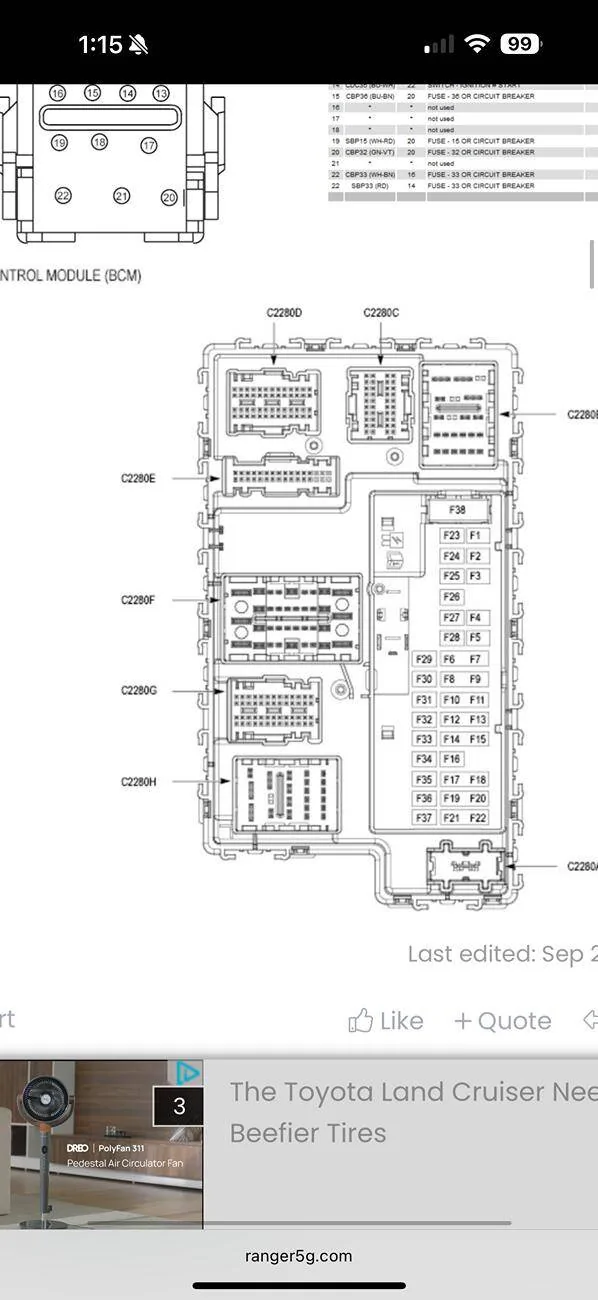
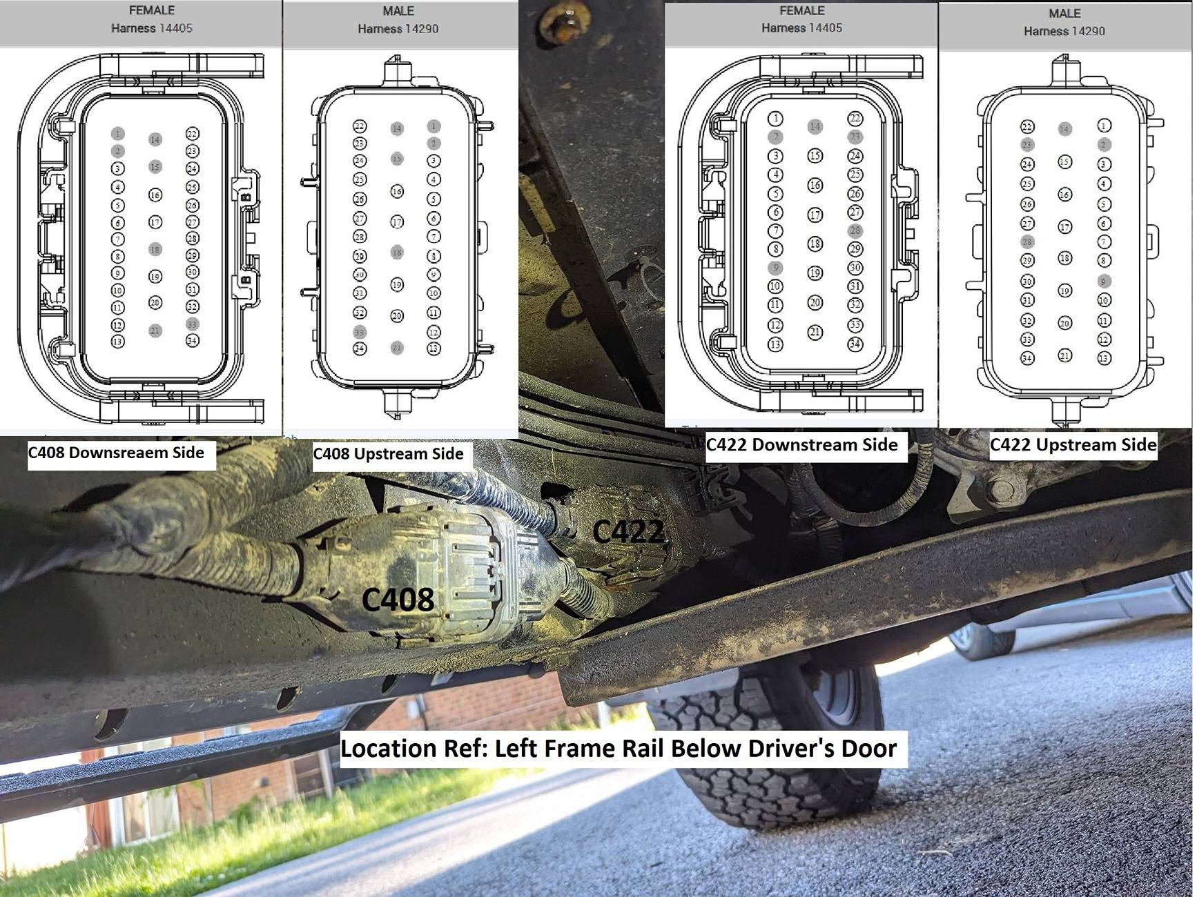
C422 Connector Location
Pins: 31 - 32 - 33 and 34 are the MS-Can bus wires that feed the Tail Lamps and then back up to the C211 connector which you already reseated.
You do not have BLIS, but you do have the TRM (Trailer Module) that uses the can bus data feed.
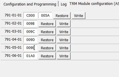
You are able to communicate to the TRM, but it is also reporting a (Config Not Complete) Msg

(OK) [12:31:02.252] Disconnected
(WARN) [12:31:05.480] Checking FTDI #1:223230240103...
(OK) [12:31:06.120] Connection to adapter has been established: FTDI #1:223230240103
(OK) [12:31:06.120] Adapter: OBDLink EX r2.7.1 STN2232 v5.9.5 (ELM327 v1.4b)
(OK) [12:31:06.195] Connection to vehicle has been established
(OK) [12:31:06.395] Vehicle: Ford Ranger/Courier/Mazda B-Series EcoBoost Gasoline Turbocharged Direct Injection 2.3L 2020 ( 2020 MY ), VIN: 1FT*********66391
(OK) [12:31:08.392] Found module: PCM - Powertrain Control Module
(WARN) [12:31:16.351] DTCs in PCM: U0164:00-2F
(OK) [12:31:16.507] Found module: OBDII - On Board Diagnostic II
(OK) [12:31:17.158] Found module: APIM - Accessory Protocol Interface Module
(WARN) [12:31:17.325] DTCs in APIM: U0256:00-0A
(OK) [12:31:17.616] Found module: DCDC - DC to DC Converter Control Module
(OK) [12:31:19.480] Found module: BdyCM - Body Control Module
(WARN) [12:31:22.717] DTCs in BdyCM: B1323:11-48, U3006:16-08, U3007:16-08, U3013:16-08, U3014:16-08, B115E:08-08, U0256:87-0A
(OK) [12:31:23.013] Found module: BECMB - Battery Energy Control Module B
(OK) [12:31:26.781] Found module: FCIM - Front Controls Interface Module
(WARN) [12:31:26.802] Module FCIM has no DTC function
(OK) [12:31:27.698] Found module: ATCM - All Terrain Control Module
(OK) [12:31:28.097] Found module: TRM - Trailer Module
(WARN) [12:31:28.157] DTCs in TRM: U2100:00-2F
(OK) [12:31:30.368] Found module: OCS - Occupant Classification System Module
(OK) [12:31:31.293] Found module: ABS - Antilock braking system
(WARN) [12:31:31.952] DTCs in ABS: U3003:16-08, C101A:16-08
(OK) [12:31:34.259] Found module: TCU - Telematic Control Unit Module
(OK) [12:31:34.853] Found module: RTM - Radio Transceiver Module
(OK) [12:31:36.569] Found module: RCM - Restraint Control Module
(WARN) [12:31:36.808] DTCs in RCM: U0557:82-0A
(OK) [12:31:37.896] Found module: PSCM - Power Steering Control Module
(OK) [12:31:38.456] Found module: ACM - Audio Control Module
(WARN) [12:31:38.576] DTCs in ACM: U0256:00-0A
(OK) [12:31:38.707] Found module: SCCM - Steering Column Control Module
(OK) [12:31:39.060] Found module: IPC - Instrument Panel Control Module
(WARN) [12:31:39.260] DTCs in IPC: U0104:00-08, U0439:82-08, U0557:00-0A, U0557:82-0A, P0460:13-08
(OK) [12:31:39.544] Found module: GWM - Gateway Module A
(OK) [12:31:40.023] Found module: IPMA - Image Processing Module A
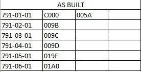
Here is the APIM as built file:
Sponsored