
airline tech
Well-Known Member
- Joined
- Aug 24, 2022
- Threads
- 28
- Messages
- 4,499
- Reaction score
- 8,592
- Location
- Midwest - KS
- Vehicle(s)
- 2022 Ranger Lariat-Super Crew, Cactus Gray
- Occupation
- Aircraft Tech
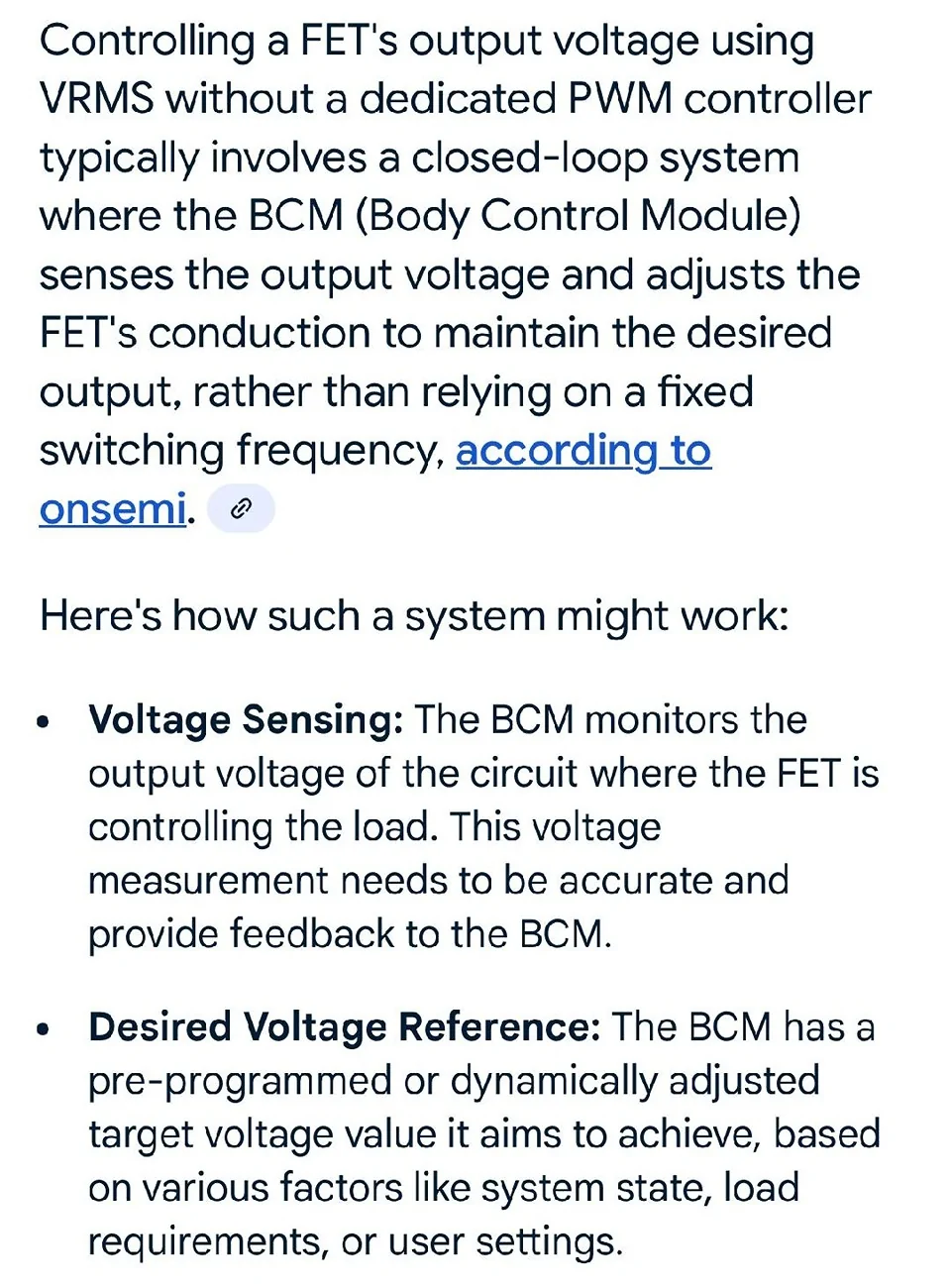
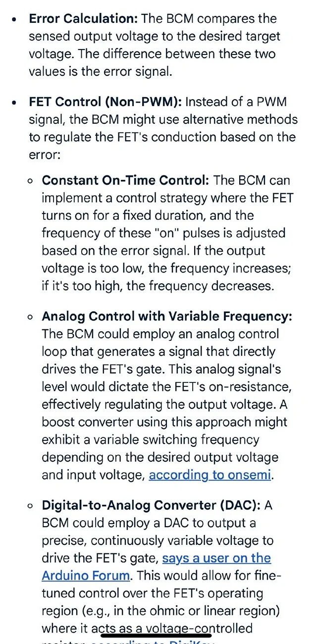
I have tried various searches and only can find this information - However this is from (AI) on the phone - well tried same search with computer and it would not come up with the same info - GRR


One word was cut off - (Voltage Controlled Resistor)
So being that the As-Built file for the Stop Lamps has it set as (VRMS) we know that VRMS is being used instead of Duty (PWM)
We also know this about the FET:
A Field Effect Transistor (FET) is a type of transistor that the control module software uses to control and monitor current flow on module outputs. The Field Effect Transistor (FET) protection strategy prevents module damage in the event of excessive current flow.
and we know
The FET will also trigger for (Under Current)
What that specific (variance range of the current) Upper & Lower Limits is?= (Unknown)
We know that Current = The rate of the flow = (Amps)
We Know that the (TBC) module has a 5 Amp fused input from the BPP Circuit, so lets guesstimate that the approximate circuit amperage for the TBC is about 3.0 amps, to complete the circuit input that the Brake Pedal has been pressed - Again Guesstimate -Using the 25% rule for Fuse Sizing.
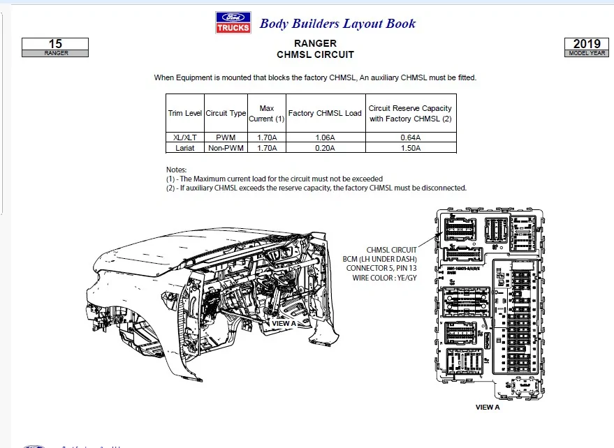
So if we were to simply change the input from that 5-Amp fused source to the CHML input we will be adding a (Approximate) 3.0-Amp current draw to the FET circuit and possibly triggering a trip of the circuit with associated DTC's.
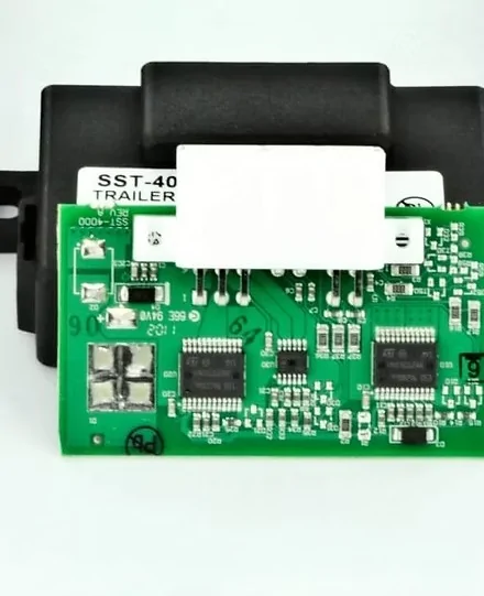
This is what brings in the Lumen Module, it operates and functions within the set (variance) of the FETs (Upper and Lower) Current Limits - Whatever those limits are?
I have always been kind of stumped on exactly how the BCM-FET protection worked - as it is known the BCM is finicky on adding extras to its circuits, the above (AI) finds makes some sense on how its controlled but it would be nice to know (more specific) variance levels of the Upper & Lower current (Triggering the FET) Off, killing the circuit.
So all the previous posted knowledge of this being a PWM signal (I do not see it), cleaning of the signal (YES) as the BCM and the FET are in control of that signal and the input of that signal to the Lumen Module is needed solely to keep the BCM & Its FET circuit happy then convert that signal into a range the TBC will recognize
I may not be precisely on point here, but I think this is possibly the true reasoning for the Lumen Module. I am confident is ties into the FET Protection of the circuit as the main factor.
As far as Brake Lights (Pulse) in a AEB event - I would think that I would find something in the As-Built files that would program that into the circuit operation (I do not see it) so YES I see a brake light (ON) with that event and that's it.
From what I see - its both circuits (Stop Lamps & CHMSL) will be commanded on during a AEB and ACC braking event - the Lumen Module will see it and activate the Trailer Brakes without actual brake pedal input.
One word was cut off - (Voltage Controlled Resistor)
So being that the As-Built file for the Stop Lamps has it set as (VRMS) we know that VRMS is being used instead of Duty (PWM)
We also know this about the FET:
A Field Effect Transistor (FET) is a type of transistor that the control module software uses to control and monitor current flow on module outputs. The Field Effect Transistor (FET) protection strategy prevents module damage in the event of excessive current flow.
and we know
The FET will also trigger for (Under Current)
What that specific (variance range of the current) Upper & Lower Limits is?= (Unknown)
We know that Current = The rate of the flow = (Amps)
We Know that the (TBC) module has a 5 Amp fused input from the BPP Circuit, so lets guesstimate that the approximate circuit amperage for the TBC is about 3.0 amps, to complete the circuit input that the Brake Pedal has been pressed - Again Guesstimate -Using the 25% rule for Fuse Sizing.
So if we were to simply change the input from that 5-Amp fused source to the CHML input we will be adding a (Approximate) 3.0-Amp current draw to the FET circuit and possibly triggering a trip of the circuit with associated DTC's.
This is what brings in the Lumen Module, it operates and functions within the set (variance) of the FETs (Upper and Lower) Current Limits - Whatever those limits are?
I have always been kind of stumped on exactly how the BCM-FET protection worked - as it is known the BCM is finicky on adding extras to its circuits, the above (AI) finds makes some sense on how its controlled but it would be nice to know (more specific) variance levels of the Upper & Lower current (Triggering the FET) Off, killing the circuit.
So all the previous posted knowledge of this being a PWM signal (I do not see it), cleaning of the signal (YES) as the BCM and the FET are in control of that signal and the input of that signal to the Lumen Module is needed solely to keep the BCM & Its FET circuit happy then convert that signal into a range the TBC will recognize
I may not be precisely on point here, but I think this is possibly the true reasoning for the Lumen Module. I am confident is ties into the FET Protection of the circuit as the main factor.
As far as Brake Lights (Pulse) in a AEB event - I would think that I would find something in the As-Built files that would program that into the circuit operation (I do not see it) so YES I see a brake light (ON) with that event and that's it.
From what I see - its both circuits (Stop Lamps & CHMSL) will be commanded on during a AEB and ACC braking event - the Lumen Module will see it and activate the Trailer Brakes without actual brake pedal input.
Sponsored