
Sponsored

Ford warns that Active Cruise Control can NOT be used with an aftermarket trailer brake controller

airline tech

Well-Known Member
Joined
Aug 24, 2022
Threads
28
Messages
4,499
Reaction score
8,592
Location
Midwest - KS
Vehicle(s)
2022 Ranger Lariat-Super Crew, Cactus Gray
Occupation
Aircraft Tech
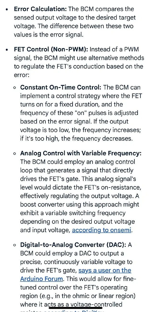
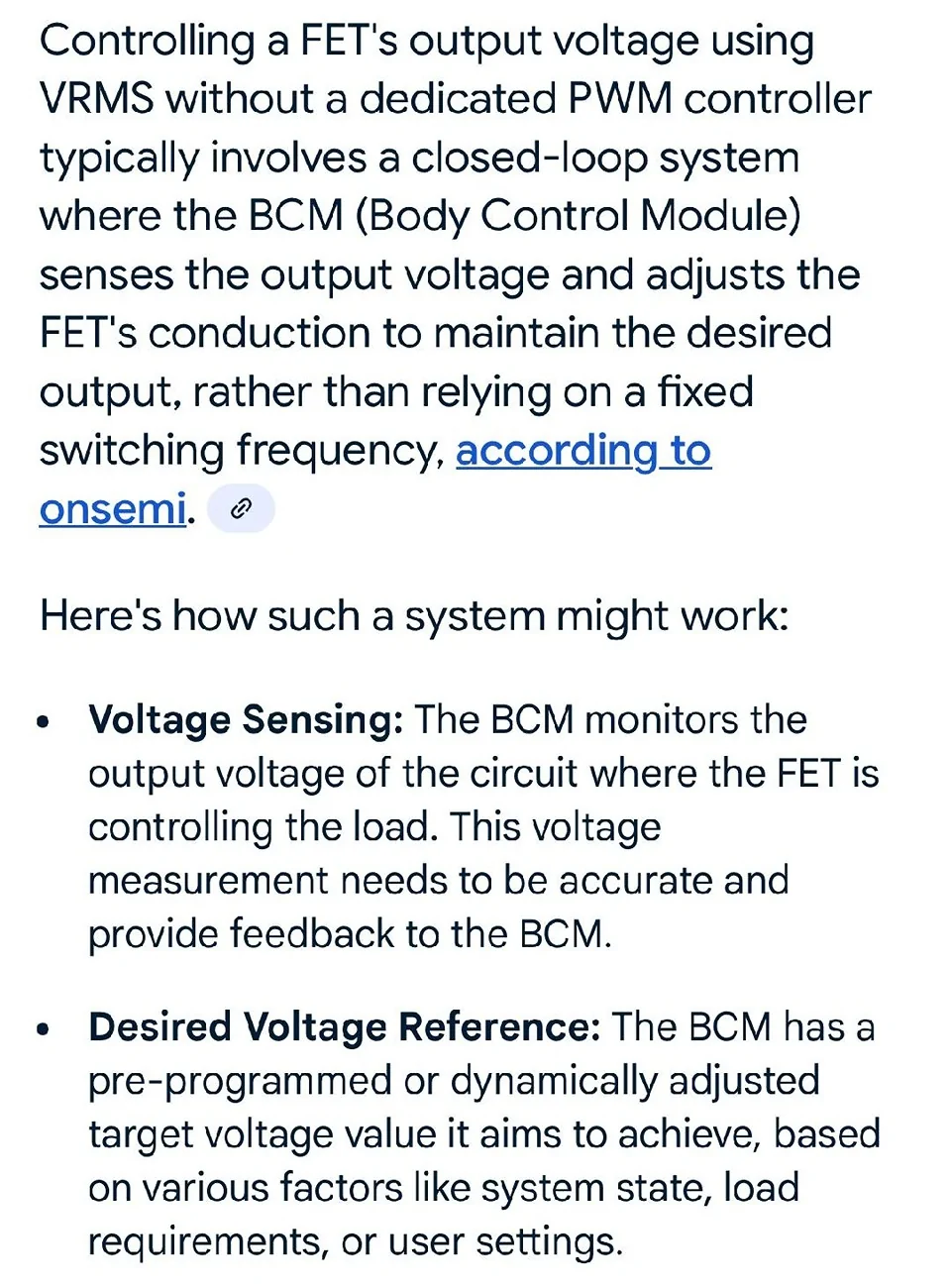
I have tried various searches and only can find this information - However this is from (AI) on the phone - well tried same search with computer and it would not come up with the same info - GRR:curse:


FET 1a.webp


FET 2a.webp


One word was cut off - (Voltage Controlled Resistor)

So being that the As-Built file for the Stop Lamps has it set as (VRMS) we know that VRMS is being used instead of Duty (PWM)

We also know this about the FET:

A Field Effect Transistor (FET) is a type of transistor that the control module software uses to control and monitor current flow on module outputs. The Field Effect Transistor (FET) protection strategy prevents module damage in the event of excessive current flow.
and we know
The FET will also trigger for (Under Current)

What that specific (variance range of the current) Upper & Lower Limits is?= (Unknown)

We know that Current = The rate of the flow = (Amps)
We Know that the (TBC) module has a 5 Amp fused input from the BPP Circuit, so lets guesstimate that the approximate circuit amperage for the TBC is about 3.0 amps, to complete the circuit input that the Brake Pedal has been pressed - Again Guesstimate -Using the 25% rule for Fuse Sizing.
So if we were to simply change the input from that 5-Amp fused source to the CHML input we will be adding a (Approximate) 3.0-Amp current draw to the FET circuit and possibly triggering a trip of the circuit with associated DTC's.

This is what brings in the Lumen Module, it operates and functions within the set (variance) of the FETs (Upper and Lower) Current Limits - Whatever those limits are?

I have always been kind of stumped on exactly how the BCM-FET protection worked - as it is known the BCM is finicky on adding extras to its circuits, the above (AI) finds makes some sense on how its controlled but it would be nice to know (more specific) variance levels of the Upper & Lower current (Triggering the FET) Off, killing the circuit.

So all the previous posted knowledge of this being a PWM signal (I do not see it), cleaning of the signal (YES) as the BCM and the FET are in control of that signal and the input of that signal to the Lumen Module is needed solely to keep the BCM & Its FET circuit happy then convert that signal into a range the TBC will recognize

I may not be precisely on point here, but I think this is possibly the true reasoning for the Lumen Module. I am confident is ties into the FET Protection of the circuit as the main factor.
As far as Brake Lights (Pulse) in a AEB event - I would think that I would find something in the As-Built files that would program that into the circuit operation (I do not see it) so YES I see a brake light (ON) with that event and that's it.
From what I see - its both circuits (Stop Lamps & CHMSL) will be commanded on during a AEB and ACC braking event - the Lumen Module will see it and activate the Trailer Brakes without actual brake pedal input.
Sponsored
 

RangerBill

Well-Known Member
First Name
Bob
Joined
Jun 8, 2022
Threads
3
Messages
1,659
Reaction score
2,215
Location
PA
Vehicle(s)
2019 Ford Ranger Lariat Super Crew FX4
Occupation
retired
My observations:

What I have learned about the stop light circuit (taillight and CHMSL) is that the FET outputs for these lights is not PWM and not voltage regulated. My DC and AC meter readings show no AC voltage and the DC voltage is always very close to measured battery voltage, so no voltage regulation is implied. Your scope measurements confirm this. When the engine is running, the stop light voltages are 14.6 VDC on my truck and when the engine is not running, the voltage was 12.5 VDC. Both voltages corresponded to battery voltage within a couple of tenths of a volt. The FET is being used as an electronic on-off switch (in place of a relay). The BCM has current detection circuity monitoring each FET output circuit. When an overcurrent is detected (such as a short circuit), it switches off the FET output fast enough that no fuse is blown and reports it as a DTC. The current feedback circuitry can also detect an open lamp and report it the instrument panel to alert the driver.

The taillight LEDs appear to have built in LED driver circuitry so they don't need a PWM or regulated power source to limit current through the LED. In the CHMSL assembly, I did observe LED driver circuitry on its circuit board. With onboard LED driver circuitry, full battery voltage can be applied to power the light assemblies without the need for external voltage regulation. With onboard driver circuitry a varying voltage source (battery voltage fluctuation) results in a constant brightness from the lamp assemblies.

As for the Lumen module for the trailer brake controller, it provides circuit isolation so the brake controller doesn't interfere with the BCM control of the truck stop lamps.
 

RangerBill

Well-Known Member
First Name
Bob
Joined
Jun 8, 2022
Threads
3
Messages
1,659
Reaction score
2,215
Location
PA
Vehicle(s)
2019 Ford Ranger Lariat Super Crew FX4
Occupation
retired
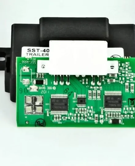
Here is a picture of the Lumen SST-4000G. Whatever its purpose, it has a lot of circuitry inside.
Lumen SST-4000G.webp
 

airline tech

Well-Known Member
Joined
Aug 24, 2022
Threads
28
Messages
4,499
Reaction score
8,592
Location
Midwest - KS
Vehicle(s)
2022 Ranger Lariat-Super Crew, Cactus Gray
Occupation
Aircraft Tech
From the Ranger Body & Equipment Manual:
I do not think I have ever seen this in the circuit (Blunt Cut Wire) but it does give some indication of (Current Output)
So (IF) the Ranger actually had this wire - it would be spliced into the CHMSL power feed
so we can assume that the (Maximum) total current load is about 1.75 Amps for the CHMSL circuit.

Copy & Paste from the manual

Brake (Stop) Lamps)
Provision for additional Brake (Stop) Lamps is
available via a blunt cut wire located near to the
Centre High Mount Stop Lamp (CHMSL). The
blunt cut wire can support a current load of 1.75
Amps steady state (at 13.5 Volts).

With the CHMSL having a separate feed this would only be the CHMSL circuit.
And this circuit (if we had it) may be a completely separate feed for (ADDITIONAL) CHMSL

And then the manual slightly contradicts itself in another section
If the Blunt Cut is spliced into the same CHMSL as the main light (Conflicting info)

Centre High Mount Stop Lamp (CHMSL)
NOTE: When replacing the factory fitted CHMSL
with a canopy mounted CHMSL, the same type
must be used. Replace a bulb/incandescent type
only with a bulb/incandescent. Replace an LED
type only with an LED type.
NOTE: The maximum current load that can be
applied to the CHMSL circuit is 2.5A for either
incandescent globes or LED lamps. Do not exceed
the rated load.

Either way, we have some indication of the max load (current) and I can assume its the 2.5 Amp limit.
Since I do not know the wattage of the CHMSL (LED) off hand, I will use the 912 Bulb as a guide-
Its rated as 12.8 Watts, so it would calculate to about 1.0 amps (current) @ the 13.5v ref voltage used above.
So you have about 1.5 amps before you max out the current and trip the FET.

With the BPP (input) to the TBC being on a 5-Amp fused circuit and the CHMSL using a 2.5 amp (FET) protected circuit is what created the reason for the Lumen Module.
and part of that CHMSL circuit is being used up by the light bulb and or LED itself.

I could not find the Specs for the Rear Brake/Stop Light circuit as the circuit max current load would be different.
Each side would draw about 1.5 Amps with using 21.0 Watts as a ref. for the bulb. I suspect a similar max amp for the circuit but slightly higher.


Other Lighting Outputs:

Position (Park) Lamps)
Additional Position (Park) lamps can be
connected via jumper harness or a pre-installed
and tagged blunt cut wire located in the LHS cowl
area, as part of the vehicles existing position lamp
circuit wiring. The existing position lamp circuit
wiring can support a current load of 3.1 Amps
steady state at (at 13.5 Volts).

Note: We do not have this Blunt Cut Wire

Lamps – Hazard / Direction
Indication
The maximum permissible load with the standard
system is:
• 3 x 5W – front and rear indicators + side
repeaters (Left Hand Side)
• 3 x 5W – front and rear indicators + side
repeaters (Right Hand Side)
NOTE: The maximum output of the turn/hazard
signal BCM outputs is 3.2 amps.
Turn/Hazard lamp signals are available as an
output from the BCM.
 
Last edited:

t4thfavor

Well-Known Member
First Name
Chance
Joined
Feb 5, 2019
Threads
32
Messages
2,607
Reaction score
2,357
Location
Michigan
Vehicle(s)
2019 Ranger XLT FX4 Fox 2.0, 2011 Ford Edge Sport
This is a solved problem already… just tap the circuit hook up a data logger and drive around with acc on for a little bit. You’ll see that it has a pulsed output (visibly not pwm at high frequencies) and the lumen module listens for that and outputs a steady brake signal for the controller to cue off of. The lumen module has a bunch of electronics because it’s real-time and has to be reliable as it’s attached to a safety system.


RangerBill

Well-Known Member
First Name
Bob
Joined
Jun 8, 2022
Threads
3
Messages
1,659
Reaction score
2,215
Location
PA
Vehicle(s)
2019 Ford Ranger Lariat Super Crew FX4
Occupation
retired
This is a solved problem already… just tap the circuit hook up a data logger and drive around with acc on for a little bit. You’ll see that it has a pulsed output (visibly not pwm at high frequencies) and the lumen module listens for that and outputs a steady brake signal for the controller to cue off of. The lumen module has a bunch of electronics because it’s real-time and has to be reliable as it’s attached to a safety system.
So, you are saying that the stop lamps pulse on and off during an emergency braking event or slowing the truck using adaptive cruise control? I had suspected this as stated in my earlier post #205.
https://www.ranger5g.com/forum/thre...ket-trailer-brake-controller.2892/post-808453
 

airline tech

Well-Known Member
Joined
Aug 24, 2022
Threads
28
Messages
4,499
Reaction score
8,592
Location
Midwest - KS
Vehicle(s)
2022 Ranger Lariat-Super Crew, Cactus Gray
Occupation
Aircraft Tech
All I can confirm (So Far) is that yes there is a (Can Bus) data transmission to activate the Brake Lights when (ACC or AEB) is active - however I cannot find in the As-Built data what frequency it uses for that control (at those events) - so if the Brake Lights do actively pulse then the BCM would be quickly turning on and off the (FET) via the output control voltage setting of VRMS, as this is the only voltage control output I can find for the circuit.
Yes it would make sense for the Brake Light to pulse in these events to get the attention of the drivers behind you - only for the this event Ford does not give details of this operation, so the only true way to see it is to duplicate the tap ins, and drive using Active Cruise and get it in the proper situation where the system would actively apply the brakes and note if the lighting output is the same vs pulsing.
It appears its all behind the scenes programming, I would think that there would be a As-Built output control to configure that (pulse)

So far I feel its more than just the (Pulse- Light Output) if it is actually pulsing under those conditions, I think it more tied into the limitations of the (FET) circuit and its limits of amperage draw to allow a direct connection to the TBC without the Lumen Module.
So if the lights pulse - the Lumen Module covers 2 separate issues of the circuit.
The Limitation of the (FET) and the Pulsating Voltage Signal
 

t4thfavor

Well-Known Member
First Name
Chance
Joined
Feb 5, 2019
Threads
32
Messages
2,607
Reaction score
2,357
Location
Michigan
Vehicle(s)
2019 Ranger XLT FX4 Fox 2.0, 2011 Ford Edge Sport
All I can confirm (So Far) is that yes there is a (Can Bus) data transmission to activate the Brake Lights when (ACC or AEB) is active - however I cannot find in the As-Built data what frequency it uses for that control (at those events) - so if the Brake Lights do actively pulse then the BCM would be quickly turning on and off the (FET) via the output control voltage setting of VRMS, as this is the only voltage control output I can find for the circuit.
Yes it would make sense for the Brake Light to pulse in these events to get the attention of the drivers behind you - only for the this event Ford does not give details of this operation, so the only true way to see it is to duplicate the tap ins, and drive using Active Cruise and get it in the proper situation where the system would actively apply the brakes and note if the lighting output is the same vs pulsing.
It appears its all behind the scenes programming, I would think that there would be a As-Built output control to configure that (pulse)

So far I feel its more than just the (Pulse- Light Output) if it is actually pulsing under those conditions, I think it more tied into the limitations of the (FET) circuit and its limits of amperage draw to allow a direct connection to the TBC without the Lumen Module.
So if the lights pulse - the Lumen Module covers 2 separate issues of the circuit.
The Limitation of the (FET) and the Pulsating Voltage Signal
The lumen model sees “blinky blinky” and using a separate 12v source outputs “not blinky blinky” to the brake controller.
 

airline tech

Well-Known Member
Joined
Aug 24, 2022
Threads
28
Messages
4,499
Reaction score
8,592
Location
Midwest - KS
Vehicle(s)
2022 Ranger Lariat-Super Crew, Cactus Gray
Occupation
Aircraft Tech
The issue I have is that from that post about why the Lumen Module was required did not provide documented information with it.
Being that 1 - It was stated it was a PWM signal - This has been proven to be incorrect information.

Now to be honest, I do not have a TBC installed and most likely will never have a need for one.
My quest was to find documented information on how the system operates, in ALL descriptions of the systems - it only states the brakes are pre-charged to provide a more aggressive and faster braking application by driver and or automatically apply the brakes.
I dug into the Brake/Stop Lamp Circuits & CHMSL Circuit, noted that the FET control limited the output and noted that tapping the circuit for a direct feed into the TBC would most likely trigger faults on the FET.

I can see that - As it was questioned - Do the brake lights trigger in a ACC or AEB event? - YES

But I do not see them - being a pulsed voltage. I think they are strictly on and steady and I think this is more of a government issue for the US Vehicles. To my knowledge flashing brake lights is considered illegal by our government, thus this would be why its mostly aftermarket mods to get this feature.

Here is the AEB brake light data transmission:

Emergency brake lamp requestABS moduleHS-CAN2
  • GWM
Emergency brake lamp requestGWMHS-CAN1
  • BCM


Here is the ACC brake light data transmission and regular brake light data transmission.
The Stop Lamp Brake Request - is controlled by the ABS Module.
The Stop Lamp request is the Brake Light Switch (Input)
Where this data chart falls short is - does the TRM also receive the same stop lamp request.
Logically, yes as the BCM is receiving a signal of data to power the brake light circuits


Stop lamp brake requestABS moduleHS-CAN2
  • GWM
Stop lamp brake requestGWMHS-CAN1
  • BCM
Stop lamp requestBCMHS-CAN1
  • GWM
Stop lamp requestGWMMS-CAN
  • TRM

The point is that we assume its a pulsed brake light output and no real confirmation of data to back it up and with the information I can find - its just a steady normal brake light output that is only bypassing the switch for the can bus to power the 2 circuits.

If I am wrong - I will admit I am wrong - no issues, but unless someone can provide documented information that the brake lights actually pulse in a ACC or AEB event, I am staying with its just a steady output.

Did I see some type of voltage control with the FET circuit - Yes and confirm that the voltage outputs do vary between the switch and lights and I also can confirm this circuit has a limitation for what can be added.

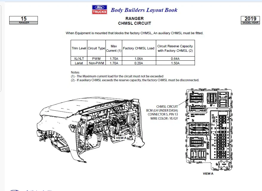
Ref this:
Note this is from the 2019 Body Builders Manual. note the XL/XLT is listed as PWM, however through all my as built compares - all trims are (NON-PWM) which as set as VRMS vs Duty (PWM)
but 2 pieces of this information is important (Max Current Load) for the circuit and (Reserve Capacity)
So, I read this and factor in tapping this circuit direct into the TBC would exceed the circuit capacity, now since I do not know the specs of that TBC input for brake applied, I can only use what that circuit is fused for (its a 5-Amp fused circuit) generally this would mean that that 5-Amp circuit is actually using about 1.5 to 3.0 Amps of current and provide a safe buffer zone.
Thus maxing out or near maxing out the circuit - if tapped directly to the TBC

This is why I believe the Lumen Module was implemented, it provided a way to use the CHMSL circuit and also be well under the Max Current of the circuit protection of the FET, the internals of the Lumen Module allows that transition - I think that is all the module is used for (Main Function)
and also clean up the signal to match what the brake pedal applied signal would be.
But its main purpose is to play nice with the FET protected circuit.

CHMSL Outputs.webp
 

t4thfavor

Well-Known Member
First Name
Chance
Joined
Feb 5, 2019
Threads
32
Messages
2,607
Reaction score
2,357
Location
Michigan
Vehicle(s)
2019 Ranger XLT FX4 Fox 2.0, 2011 Ford Edge Sport
The issue I have is that from that post about why the Lumen Module was required did not provide documented information with it.
Being that 1 - It was stated it was a PWM signal - This has been proven to be incorrect information.

Now to be honest, I do not have a TBC installed and most likely will never have a need for one.
My quest was to find documented information on how the system operates, in ALL descriptions of the systems - it only states the brakes are pre-charged to provide a more aggressive and faster braking application by driver and or automatically apply the brakes.
I dug into the Brake/Stop Lamp Circuits & CHMSL Circuit, noted that the FET control limited the output and noted that tapping the circuit for a direct feed into the TBC would most likely trigger faults on the FET.

I can see that - As it was questioned - Do the brake lights trigger in a ACC or AEB event? - YES

But I do not see them - being a pulsed voltage. I think they are strictly on and steady and I think this is more of a government issue for the US Vehicles. To my knowledge flashing brake lights is considered illegal by our government, thus this would be why its mostly aftermarket mods to get this feature.

Here is the AEB brake light data transmission:

Emergency brake lamp requestABS moduleHS-CAN2
  • GWM
Emergency brake lamp requestGWMHS-CAN1
  • BCM


Here is the ACC brake light data transmission and regular brake light data transmission.
The Stop Lamp Brake Request - is controlled by the ABS Module.
The Stop Lamp request is the Brake Light Switch (Input)
Where this data chart falls short is - does the TRM also receive the same stop lamp request.
Logically, yes as the BCM is receiving a signal of data to power the brake light circuits


Stop lamp brake requestABS moduleHS-CAN2
  • GWM
Stop lamp brake requestGWMHS-CAN1
  • BCM
Stop lamp requestBCMHS-CAN1
  • GWM
Stop lamp requestGWMMS-CAN
  • TRM

The point is that we assume its a pulsed brake light output and no real confirmation of data to back it up and with the information I can find - its just a steady normal brake light output that is only bypassing the switch for the can bus to power the 2 circuits.

If I am wrong - I will admit I am wrong - no issues, but unless someone can provide documented information that the brake lights actually pulse in a ACC or AEB event, I am staying with its just a steady output.

Did I see some type of voltage control with the FET circuit - Yes and confirm that the voltage outputs do vary between the switch and lights and I also can confirm this circuit has a limitation for what can be added.

Ref this:
Note this is from the 2019 Body Builders Manual. note the XL/XLT is listed as PWM, however through all my as built compares - all trims are (NON-PWM) which as set as VRMS vs Duty (PWM)
but 2 pieces of this information is important (Max Current Load) for the circuit and (Reserve Capacity)
So, I read this and factor in tapping this circuit direct into the TBC would exceed the circuit capacity, now since I do not know the specs of that TBC input for brake applied, I can only use what that circuit is fused for (its a 5-Amp fused circuit) generally this would mean that that 5-Amp circuit is actually using about 1.5 to 3.0 Amps of current and provide a safe buffer zone.
Thus maxing out or near maxing out the circuit - if tapped directly to the TBC

This is why I believe the Lumen Module was implemented, it provided a way to use the CHMSL circuit and also be well under the Max Current of the circuit protection of the FET, the internals of the Lumen Module allows that transition - I think that is all the module is used for (Main Function)
and also clean up the signal to match what the brake pedal applied signal would be.
But its main purpose is to play nice with the FET protected circuit.

CHMSL Outputs.jpeg
You can flash any lights you want on your vehicle as long as they aren't blue. The number of flashing brake center lights from every vendor is proof.

FWIW, I've had a brake controller installed (teknosha PIII) and towed thousands of miles without issue since February of 2019 which was years before there was a lumen module to solve the AEB "issue".
 

WhyNot21

Well-Known Member
First Name
Mike
Joined
Apr 10, 2021
Threads
7
Messages
578
Reaction score
1,720
Location
FL
Vehicle(s)
2021 Ranger Lariat FX4 Screw 501A ...
Occupation
EE
You can flash any lights you want on your vehicle as long as they aren't blue. The number of flashing brake center lights from every vendor is proof.
Sorry, that's incorrect. Even though many dealers add it as an option, it doesn't make it any less illegal.

"Under the Federal regulations in the United States, motor vehicles must be manufactured so that the third brake light (or "center highmounted stop lamp" as we call it) and all other stop lamps are steady-burning when they are in use.

After the vehicle is sold, Federal law prohibits any manufacturer, dealer, distributor, or motor vehicle repair business from installing the sensor to modify the performance of the third brake light and cause it to flash."


LINK to one of many NHSTA replies on the subject.
 

t4thfavor

Well-Known Member
First Name
Chance
Joined
Feb 5, 2019
Threads
32
Messages
2,607
Reaction score
2,357
Location
Michigan
Vehicle(s)
2019 Ranger XLT FX4 Fox 2.0, 2011 Ford Edge Sport
OK, well I see it dozens of times every day while commuting. I guess everyone just has an aftermarket flasher.

Here's a ranger raptor showing adaptive cruise applying the brakes and showing a steady brake light under automatic braking.

Sponsored


Top