Sponsored

Restraints Indicator Lamp Warning, Radio and Climate Physical Buttons (FCIM) not working, No Outside Temperature, No Start/Stop Either

RangerLife

Member
First Name
Anthony
Joined
Jan 8, 2024
Threads
0
Messages
22
Reaction score
8
Location
USA
Vehicle(s)
2020 Ford Ranger
We need to address the highest possible and that is - the FCIM has dumped the VIN#
I noted that is the DTC (Run) the FCIM is not (On-line) on the network.
All Codes are (Communication) related and most are previously set and not current.

You can try clearing all the codes to clean it up and then do another - Scan

When you load Forscan and view the Module List - Do you see the FCIM in the list?
If yes, then you are able to get into the (As-Built) files and view the VIN# lines I previously posted.

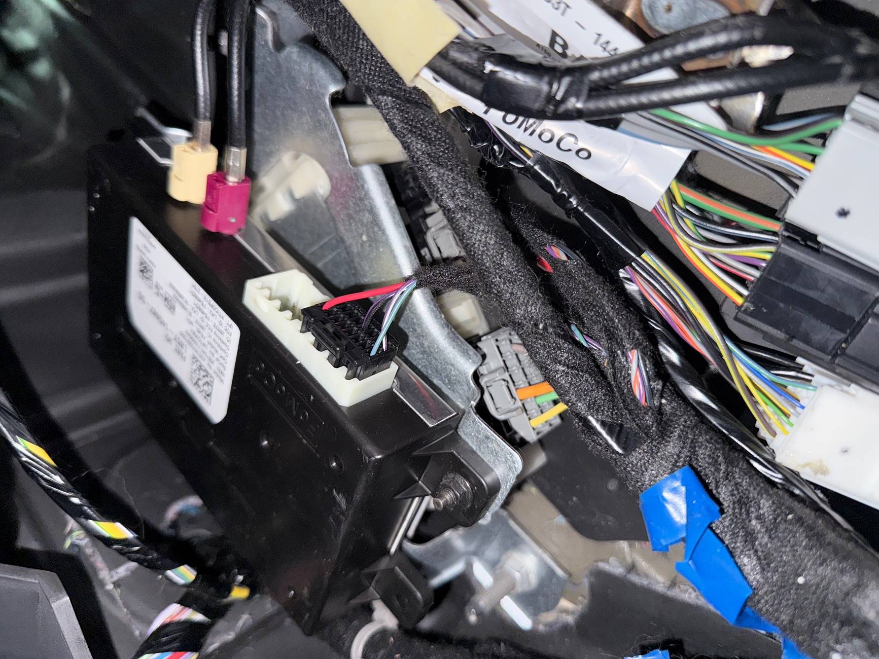
Just an operational note: The FCIM gets its power from the (BCM - Fuse Box (Fuse #12)
Pull that fuse for 5-Minutes and reinstall.
So, with Fuse #12 providing power to the FCIM, it takes MS-CAN Bus data to actually let it power up-so basically the data input is the (Switch) to turn it on.
With this module having the (VIN#) validation embedded into it, the other modules mainly the BCM have to verify the VIN# matches (programming) before the FCIM will allow the (Ignition Switch Position-Run) command to let the FCIM to power up.

From you (DTC-Run) I can see the TRM is getting power and Can Bus Com, so with that info the
MS-CAN Bus is good up to the TRM, next in line is the FCIM which is lost.

So, one of the following is the issue:
1. FCIM (As-Built) VIN# dumped and does not match your actual VIN#
2. FCIM has lost Power Feed from Fuse #12 or Fuse #12 is blown - Try 5-Minute Reset (mentioned above)
3. MS-CAN Bus data issue between the TRM & FCIM

Let's start with 1 & 2 and go from there.
FCIM is not showing up on the list; I cleared codes; pulled the fused, waited 5 min, and then re-booted the truck here are the codes:

===PCM DTC U0164:00-6C===
Code: U0164 - Lost Communication With HVAC Control Module 'A'

Status (-6C):
- DTC Maturing - Intermittent at Time of Request
- Malfunction Indicator Lamp is Off for this DTC
- Test not complete

Module: Powertrain Control Module

Freeze Frame #1:

Freeze Frame #2:
-MODULE_VOLTAGE: 1.5 V - Control Module Voltage
-SPARKADV: -28.00 ° - Spark Advance
===END PCM DTC U0164:00-6C===

===OBDII DTC None===
Successful DTC reading, no error codes found

Module: On Board Diagnostic II

===END OBDII DTC None===

===APIM DTC U0256:00-0A===
Code: U0256 - Lost Communication With Front Controls Interface Module 'A'

Status (-0A):
- DTC Present at Time of Request
- Malfunction Indicator Lamp is Off for this DTC

Module: Accessory Protocol Interface Module

===END APIM DTC U0256:00-0A===

===DCDC DTC None===
Successful DTC reading, no error codes found

Module: DC to DC Converter Control Module

===END DCDC DTC None===

===BdyCM DTC U0256:87-08===
Code: U0256 - Lost Communication With Front Controls Interface Module 'A'

Additional Fault Symptom :)87):
- Missing Message

Status (-08):
- Previously Set DTC - Not Present at Time of Request
- Malfunction Indicator Lamp is Off for this DTC

Module: Body Control Module

===END BdyCM DTC U0256:87-08===

===BECMB DTC None===
Successful DTC reading, no error codes found

Module: Battery Energy Control Module B

===END BECMB DTC None===

===ATCM DTC None===
Successful DTC reading, no error codes found

Module: All Terrain Control Module

===END ATCM DTC None===

===TRM DTC U2100:00-2F===
Code: U2100 - Initial Configuration Not Complete

Status (-2F):
- DTC Present at Time of Request
- Malfunction Indicator Lamp is Off for this DTC

Module: Trailer Module

===END TRM DTC U2100:00-2F===

===OCS DTC None===
Successful DTC reading, no error codes found

Module: Occupant Classification System Module

===END OCS DTC None===

===ABS DTC None===
Successful DTC reading, no error codes found

Module: Antilock braking system

===END ABS DTC None===

===TCU DTC None===
Successful DTC reading, no error codes found

Module: Telematic Control Unit Module

===END TCU DTC None===

===RTM DTC None===
Successful DTC reading, no error codes found

Module: Radio Transceiver Module

===END RTM DTC None===

===RCM DTC U0557:82-08===
Code: U0557 - Invalid Data Received From Front Controls Interface Module 'A'

Additional Fault Symptom :)82):
- Alive/Sequence Counter Incorrect/Not Updated

Status (-08):
- Previously Set DTC - Not Present at Time of Request
- Malfunction Indicator Lamp is Off for this DTC

Module: Restraint Control Module

Freeze Frame #1:
-EVENT_TIME: 140861042 s (Sat Mar 29 18:20:28 2025) - Event time
-TOTAL_DISTANCE: 30209 miles - Total Distance

Freeze Frame #2:
-EVENT_TIME: 140861042 s (Sat Mar 29 18:20:28 2025) - Event time
-TOTAL_DISTANCE: 30209 miles - Total Distance
===END RCM DTC U0557:82-08===

===PSCM DTC None===
Successful DTC reading, no error codes found

Module: Power Steering Control Module

===END PSCM DTC None===

===ACM DTC U0256:00-0A===
Code: U0256 - Lost Communication With Front Controls Interface Module 'A'

Status (-0A):
- DTC Present at Time of Request
- Malfunction Indicator Lamp is Off for this DTC

Module: Audio Control Module

===END ACM DTC U0256:00-0A===

===SCCM DTC None===
Successful DTC reading, no error codes found

Module: Steering Column Control Module

===END SCCM DTC None===

===IPC DTC U0557:00-0A===
Code: U0557 - Invalid Data Received From Front Controls Interface Module 'A'

Status (-0A):
- DTC Present at Time of Request
- Malfunction Indicator Lamp is Off for this DTC

Module: Instrument Panel Control Module

===END IPC DTC U0557:00-0A===

===IPC DTC U0557:82-0A===
Code: U0557 - Invalid Data Received From Front Controls Interface Module 'A'

Additional Fault Symptom :)82):
- Alive/Sequence Counter Incorrect/Not Updated

Status (-0A):
- DTC Present at Time of Request
- Malfunction Indicator Lamp is Off for this DTC

Module: Instrument Panel Control Module

===END IPC DTC U0557:82-0A===

===GWM DTC None===
Successful DTC reading, no error codes found

Module: Gateway Module A

===END GWM DTC None===

===IPMA DTC None===
Successful DTC reading, no error codes found

Module: Image Processing Module A

===END IPMA DTC None===
Sponsored


RangerBill

Well-Known Member
First Name
Bob
Joined
Jun 8, 2022
Threads
3
Messages
1,613
Reaction score
2,144
Location
PA
Vehicle(s)
2019 Ford Ranger Lariat Super Crew FX4
Occupation
retired
FCIM is not showing up on the list; I cleared codes; pulled the fused, waited 5 min, and then re-booted the truck here are the codes:

===PCM DTC U0164:00-6C===
Code: U0164 - Lost Communication With HVAC Control Module 'A'

Status (-6C):
- DTC Maturing - Intermittent at Time of Request
- Malfunction Indicator Lamp is Off for this DTC
- Test not complete

Module: Powertrain Control Module

Freeze Frame #1:

Freeze Frame #2:
-MODULE_VOLTAGE: 1.5 V - Control Module Voltage
-SPARKADV: -28.00 ° - Spark Advance
===END PCM DTC U0164:00-6C===

===OBDII DTC None===
Successful DTC reading, no error codes found

Module: On Board Diagnostic II

===END OBDII DTC None===

===APIM DTC U0256:00-0A===
Code: U0256 - Lost Communication With Front Controls Interface Module 'A'

Status (-0A):
- DTC Present at Time of Request
- Malfunction Indicator Lamp is Off for this DTC

Module: Accessory Protocol Interface Module

===END APIM DTC U0256:00-0A===

===DCDC DTC None===
Successful DTC reading, no error codes found

Module: DC to DC Converter Control Module

===END DCDC DTC None===

===BdyCM DTC U0256:87-08===
Code: U0256 - Lost Communication With Front Controls Interface Module 'A'

Additional Fault Symptom :)87):
- Missing Message

Status (-08):
- Previously Set DTC - Not Present at Time of Request
- Malfunction Indicator Lamp is Off for this DTC

Module: Body Control Module

===END BdyCM DTC U0256:87-08===

===BECMB DTC None===
Successful DTC reading, no error codes found

Module: Battery Energy Control Module B

===END BECMB DTC None===

===ATCM DTC None===
Successful DTC reading, no error codes found

Module: All Terrain Control Module

===END ATCM DTC None===

===TRM DTC U2100:00-2F===
Code: U2100 - Initial Configuration Not Complete

Status (-2F):
- DTC Present at Time of Request
- Malfunction Indicator Lamp is Off for this DTC

Module: Trailer Module

===END TRM DTC U2100:00-2F===

===OCS DTC None===
Successful DTC reading, no error codes found

Module: Occupant Classification System Module

===END OCS DTC None===

===ABS DTC None===
Successful DTC reading, no error codes found

Module: Antilock braking system

===END ABS DTC None===

===TCU DTC None===
Successful DTC reading, no error codes found

Module: Telematic Control Unit Module

===END TCU DTC None===

===RTM DTC None===
Successful DTC reading, no error codes found

Module: Radio Transceiver Module

===END RTM DTC None===

===RCM DTC U0557:82-08===
Code: U0557 - Invalid Data Received From Front Controls Interface Module 'A'

Additional Fault Symptom :)82):
- Alive/Sequence Counter Incorrect/Not Updated

Status (-08):
- Previously Set DTC - Not Present at Time of Request
- Malfunction Indicator Lamp is Off for this DTC

Module: Restraint Control Module

Freeze Frame #1:
-EVENT_TIME: 140861042 s (Sat Mar 29 18:20:28 2025) - Event time
-TOTAL_DISTANCE: 30209 miles - Total Distance

Freeze Frame #2:
-EVENT_TIME: 140861042 s (Sat Mar 29 18:20:28 2025) - Event time
-TOTAL_DISTANCE: 30209 miles - Total Distance
===END RCM DTC U0557:82-08===

===PSCM DTC None===
Successful DTC reading, no error codes found

Module: Power Steering Control Module

===END PSCM DTC None===

===ACM DTC U0256:00-0A===
Code: U0256 - Lost Communication With Front Controls Interface Module 'A'

Status (-0A):
- DTC Present at Time of Request
- Malfunction Indicator Lamp is Off for this DTC

Module: Audio Control Module

===END ACM DTC U0256:00-0A===

===SCCM DTC None===
Successful DTC reading, no error codes found

Module: Steering Column Control Module

===END SCCM DTC None===

===IPC DTC U0557:00-0A===
Code: U0557 - Invalid Data Received From Front Controls Interface Module 'A'

Status (-0A):
- DTC Present at Time of Request
- Malfunction Indicator Lamp is Off for this DTC

Module: Instrument Panel Control Module

===END IPC DTC U0557:00-0A===

===IPC DTC U0557:82-0A===
Code: U0557 - Invalid Data Received From Front Controls Interface Module 'A'

Additional Fault Symptom :)82):
- Alive/Sequence Counter Incorrect/Not Updated

Status (-0A):
- DTC Present at Time of Request
- Malfunction Indicator Lamp is Off for this DTC

Module: Instrument Panel Control Module

===END IPC DTC U0557:82-0A===

===GWM DTC None===
Successful DTC reading, no error codes found

Module: Gateway Module A

===END GWM DTC None===

===IPMA DTC None===
Successful DTC reading, no error codes found

Module: Image Processing Module A

===END IPMA DTC None===
Did you verify that fuse F12 is good? Have you cleared all DTCs and rescanned to eliminate the non-active codes?
 

airline tech

Well-Known Member
Joined
Aug 24, 2022
Threads
28
Messages
4,465
Reaction score
8,542
Location
Midwest - KS
Vehicle(s)
2022 Ranger Lariat-Super Crew, Cactus Gray
Occupation
Aircraft Tech
Honestly with the FCIM being a non-normal module I cannot confirm that the VIn# mismatch is actually the cause of it not powering up.
Meaning that IDK for sure that if the FCIM having a VIN# mismatch (if that is the case) would cause it not to power up. (Error Messages - Yes) but not powering at all - IDK

The only way to confirm (Power Loss) or (Bus Issue) is wiring checks.

But for simple things
Ensure Fuse #12 is - GOOD
Power is direct feed from the fuse to the FCIM Connector (No Inline Connectors (Between)
You may try - disconnecting and reconnecting the FCIM Connector

But for Power Check - C2402A - Pin #26
Ground Check -C2402A - Pin # 1
So, with key on (You should have power across Pins 26 & 1)

C2402A - FCIM Connector

C2402A.jpeg


The (MS-Can) Bus has a connector just before it feeds the FCIM Connector, and it is an easy access connector.
Under the Passenger Side - Kick Panel is C211
This has been a noted problem connector, and this contains the (Can-Bus) wires that feed the FCIM.
With the FCIM being the only module on the network that is offline, this may be a good spot to try a (Pull & Reseat) to see if the FCIM will come back on-line

For Ref: C211 feeds pins 17 & 18 on the FCIM Connector (MS-Can) Bus
There are more wire checks to check the Can Bus but let's start here with these simple checks to verify we have power to the FCIM, and a quick connector reseat before we dive further.

C211 - Location (note the zip-tie) from another member who had similar issue and found this connector not secured

This is located behind the passenger side kick panel - just below the glove box.

RH Kick Panel Con C211 Ziptied.jpeg
.

So, to back up to the VIN# mismatch and what actually happens (inside) the FCIM when it receives (Ignition Switch Position-Run) data - to enable the FCIM to allow operation.

Why is this important - Since I cannot see (internals) of the FCIM circuits it brings a question.

We know that the FCIM has always hot power feeding the FCIM and it takes MS-Can Bus data to enable the FCIM to power up.
The unknown is: what is happening internally (Inside) the FCIM to let that happen.

1. I am thinking that the (MS-Can) Bus - Data closes the circuit and allows the ground path.
If this is the case -for a (Off-Line) FCIM it MAY be possible to jumper the (Power & Ground) via back probing the connector - To FORCE it to power up.
This would provide a way (if the Can-Bus) register's it (On-Line) to get into the (As-Builts) and make the required changes.

From the research I have done, it's possible for a (Module Test) only and have you isolate the
Can-Bus from the circuit. (Dis-Connect) it off the Bus.

Since I cannot truly see the internals - IDK, I was just brainstorming ideas to force it to power up and (By-Pass) the MS-Can Bus Input Data (Which is basically the -SWITCH)

One way to determine if the FCIM is a switched ground vs always grounded circuit would be to Ohm the (FCIM) pins (Power & Ground) Component Side to find if it is a switched ground or constant ground.
If it's a constant ground, then the FCIM is (micro-controlled) to switch that power over to its internal circuits.

Again - Just Brainstorming for a way to force it to power up - outside of the manuals and if leaving the Can-Bus (In-Play) and not isolated will it cause issues even as a temporary power by-pass for T-Shooting.
 
Last edited:

airline tech

Well-Known Member
Joined
Aug 24, 2022
Threads
28
Messages
4,465
Reaction score
8,542
Location
Midwest - KS
Vehicle(s)
2022 Ranger Lariat-Super Crew, Cactus Gray
Occupation
Aircraft Tech
I am going to back up and redirect the T-Shoot
Now I am not seeing any Codes (Specific) for the Ambient Air Temp Sensor, so this is going to be outside the box (T-Shoot) and this direction is driven by the fact that there was damage to the area it is installed.
The manual calls for the grill to be removed to access, I would have to physically look to see if there is a shortcut to it.
I just cannot let this go - unchecked as this MAY be causing the issue.
It is a (POSSIBILITY) that this is not connected, not installed or the wiring is bad (to it)

IDK if Forscan will display this PID but a scan tool will, in the PCM Data, I have a hunch that the code U0164:00 is relating to this sensor - Although its nomenclated as (HVAC-Cont Module)
Keep in mind as I stated - the sensor or (PCM) will default the data to last known if it picks up an error. So, if you find the PID (Data) ensure it is correct.

So, a wild shot in the dark and only going by - damage area and a possible misstep in forgetting to connect it back up. Is it causing the (FCIM) not to power IDK, but if it is it would explain why they called a (Ford Tech) in to assist in clearing the issue after the repair was completed.
It is hidden and not easily viewable.


1743334124991-ob.webp
 

RangerLife

Member
First Name
Anthony
Joined
Jan 8, 2024
Threads
0
Messages
22
Reaction score
8
Location
USA
Vehicle(s)
2020 Ford Ranger
So, I checked/replaced fuse 12 Micro3 7.5A, when I did, I noticed that the fuse I purchased from Advanced Auto is slightly longer than the one installed, I tried looking online to see if there were different lengths just to make sure I wasn’t going crazy, but there aren’t so I am a bit confused on that.. however when replacing nothing happened, I tried unplugging and replying C211, nothin there, I also did remove the Grill and the temperature sensor seems to be plugged in.
I am just at a loss at this point; as for checking voltage of the pins, any recommendation on which to get that will fit in the slots?

IMG_0287.jpeg
IMG_0288.jpeg
IMG_0289.jpeg
IMG_0290.jpeg


RangerLife

Member
First Name
Anthony
Joined
Jan 8, 2024
Threads
0
Messages
22
Reaction score
8
Location
USA
Vehicle(s)
2020 Ford Ranger
Most recent code run after clearing and re-running:

ujj===PCM DTC P0463:00-64===
Code: P0463 - Fuel Level Sensor 'A' Circuit High

Status (-64):
- DTC Maturing - Intermittent at Time of Request
- Malfunction Indicator Lamp is Off for this DTC
- Test not complete

Module: Powertrain Control Module

===END PCM DTC P0463:00-64===

===PCM DTC U0164:00-6C===
Code: U0164 - Lost Communication With HVAC Control Module 'A'

Status (-6C):
- DTC Maturing - Intermittent at Time of Request
- Malfunction Indicator Lamp is Off for this DTC
- Test not complete

Module: Powertrain Control Module

===END PCM DTC U0164:00-6C===

===OBDII DTC P0463-P===
Code: P0463 - Fuel Level Sensor 'A' Circuit High

Status (-50):
- Pending - malfunction is expected to be confirmed

Module: On Board Diagnostic II

===END OBDII DTC P0463-P===

===APIM DTC U0256:00-0B===
Code: U0256 - Lost Communication With Front Controls Interface Module 'A'

Status (-0B):
- DTC Present at Time of Request
- Malfunction Indicator Lamp is Off for this DTC

Module: Accessory Protocol Interface Module

===END APIM DTC U0256:00-0B===

===DCDC DTC None===
Successful DTC reading, no error codes found

Module: DC to DC Converter Control Module

===END DCDC DTC None===

===BdyCM DTC B115E:08-08===
Code: B115E - Camera Module

Additional Fault Symptom :)08):
- Bus Signal/Message Failures

Status (-08):
- Previously Set DTC - Not Present at Time of Request
- Malfunction Indicator Lamp is Off for this DTC

Module: Body Control Module

===END BdyCM DTC B115E:08-08===

===BdyCM DTC U0256:87-08===
Code: U0256 - Lost Communication With Front Controls Interface Module 'A'

Additional Fault Symptom :)87):
- Missing Message

Status (-08):
- Previously Set DTC - Not Present at Time of Request
- Malfunction Indicator Lamp is Off for this DTC

Module: Body Control Module

===END BdyCM DTC U0256:87-08===

===BECMB DTC None===
Successful DTC reading, no error codes found

Module: Battery Energy Control Module B

===END BECMB DTC None===

===ATCM DTC None===
Successful DTC reading, no error codes found

Module: All Terrain Control Module

===END ATCM DTC None===

===TRM DTC U2100:00-2F===
Code: U2100 - Initial Configuration Not Complete

Status (-2F):
- DTC Present at Time of Request
- Malfunction Indicator Lamp is Off for this DTC

Module: Trailer Module

===END TRM DTC U2100:00-2F===

===OCS DTC None===
Successful DTC reading, no error codes found

Module: Occupant Classification System Module

===END OCS DTC None===

===ABS DTC None===
Successful DTC reading, no error codes found

Module: Antilock braking system

===END ABS DTC None===

===TCU DTC None===
Successful DTC reading, no error codes found

Module: Telematic Control Unit Module

===END TCU DTC None===

===RTM DTC None===
Successful DTC reading, no error codes found

Module: Radio Transceiver Module

===END RTM DTC None===

===RCM DTC U0557:82-08===
Code: U0557 - Invalid Data Received From Front Controls Interface Module 'A'

Additional Fault Symptom :)82):
- Alive/Sequence Counter Incorrect/Not Updated

Status (-08):
- Previously Set DTC - Not Present at Time of Request
- Malfunction Indicator Lamp is Off for this DTC

Module: Restraint Control Module

Freeze Frame #1:
-EVENT_TIME: 140861042 s - Event time
-TOTAL_DISTANCE: 30209 miles - Total Distance

Freeze Frame #2:
-EVENT_TIME: 140937704 s - Event time
-TOTAL_DISTANCE: 30209 miles - Total Distance
===END RCM DTC U0557:82-08===

===PSCM DTC None===
Successful DTC reading, no error codes found

Module: Power Steering Control Module

===END PSCM DTC None===

===ACM DTC U0256:00-0A===
Code: U0256 - Lost Communication With Front Controls Interface Module 'A'

Status (-0A):
- DTC Present at Time of Request
- Malfunction Indicator Lamp is Off for this DTC

Module: Audio Control Module

===END ACM DTC U0256:00-0A===

===SCCM DTC None===
Successful DTC reading, no error codes found

Module: Steering Column Control Module

===END SCCM DTC None===

===IPC DTC U0104:00-08===
Code: U0104 - Lost Communication With Cruise Control Module

Status (-08):
- Previously Set DTC - Not Present at Time of Request
- Malfunction Indicator Lamp is Off for this DTC

Module: Instrument Panel Control Module

===END IPC DTC U0104:00-08===

===IPC DTC U0439:82-08===
Code: U0439 - Invalid Data Received From All Terrain Control Module

Additional Fault Symptom :)82):
- Alive/Sequence Counter Incorrect/Not Updated

Status (-08):
- Previously Set DTC - Not Present at Time of Request
- Malfunction Indicator Lamp is Off for this DTC

Module: Instrument Panel Control Module

===END IPC DTC U0439:82-08===

===IPC DTC U0557:00-0A===
Code: U0557 - Invalid Data Received From Front Controls Interface Module 'A'

Status (-0A):
- DTC Present at Time of Request
- Malfunction Indicator Lamp is Off for this DTC

Module: Instrument Panel Control Module

===END IPC DTC U0557:00-0A===

===IPC DTC U0557:82-08===
Code: U0557 - Invalid Data Received From Front Controls Interface Module 'A'

Additional Fault Symptom :)82):
- Alive/Sequence Counter Incorrect/Not Updated

Status (-08):
- Previously Set DTC - Not Present at Time of Request
- Malfunction Indicator Lamp is Off for this DTC

Module: Instrument Panel Control Module

===END IPC DTC U0557:82-08===

===IPC DTC P0460:13-08===
Code: P0460 - Fuel Level Sensor A Circuit

Additional Fault Symptom :)13):
- Circuit Open

Status (-08):
- Previously Set DTC - Not Present at Time of Request
- Malfunction Indicator Lamp is Off for this DTC

Module: Instrument Panel Control Module

===END IPC DTC P0460:13-08===

===GWM DTC None===
Successful DTC reading, no error codes found

Module: Gateway Module A

===END GWM DTC None===

===IPMA DTC None===
Successful DTC reading, no error codes found

Module: Image Processing Module A

===END IPMA DTC None===
 

airline tech

Well-Known Member
Joined
Aug 24, 2022
Threads
28
Messages
4,465
Reaction score
8,542
Location
Midwest - KS
Vehicle(s)
2022 Ranger Lariat-Super Crew, Cactus Gray
Occupation
Aircraft Tech
Couple other things to try, since all we need is a way to get the FCIM to provide some kind of response (wake-up)

It is possible that the other codes (Lost Com) are stopping the FCIM from powering
So, try:

1. Disconnecting the battery for 10-Minutes, as clearing the codes had no help and they returned.

2. Sync - Reset - Hold (Seek - Fwd) Button & Power Button (on the FCIM) at the same time and see if the button input will provide (force) a communication wake.

3. With Forscan- Find the (Self-Tests) for all the modules that are registering (Lost Com)
The (Self-Tests) will provide a (Self-Reset) when it finishes.
Note: So, it does not scare you the PCM Self-Test with the engine running will command the Fan Speed to raise and if I recall it will also raise the RPM's and drop them back down (Automatically)

Just trying to cover - everything possible that may be blocking the FCIM from jumping (On-Line)
 

airline tech

Well-Known Member
Joined
Aug 24, 2022
Threads
28
Messages
4,465
Reaction score
8,542
Location
Midwest - KS
Vehicle(s)
2022 Ranger Lariat-Super Crew, Cactus Gray
Occupation
Aircraft Tech
Most recent code run after clearing and re-running:

ujj===PCM DTC P0463:00-64===
Code: P0463 - Fuel Level Sensor 'A' Circuit High

Status (-64):
- DTC Maturing - Intermittent at Time of Request
- Malfunction Indicator Lamp is Off for this DTC
- Test not complete

Module: Powertrain Control Module

===END PCM DTC P0463:00-64===

===PCM DTC U0164:00-6C===
Code: U0164 - Lost Communication With HVAC Control Module 'A'

Status (-6C):
- DTC Maturing - Intermittent at Time of Request
- Malfunction Indicator Lamp is Off for this DTC
- Test not complete

Module: Powertrain Control Module

===END PCM DTC U0164:00-6C===

===OBDII DTC P0463-P===
Code: P0463 - Fuel Level Sensor 'A' Circuit High

Status (-50):
- Pending - malfunction is expected to be confirmed

Module: On Board Diagnostic II

===END OBDII DTC P0463-P===

===APIM DTC U0256:00-0B===
Code: U0256 - Lost Communication With Front Controls Interface Module 'A'

Status (-0B):
- DTC Present at Time of Request
- Malfunction Indicator Lamp is Off for this DTC

Module: Accessory Protocol Interface Module

===END APIM DTC U0256:00-0B===

===DCDC DTC None===
Successful DTC reading, no error codes found

Module: DC to DC Converter Control Module

===END DCDC DTC None===

===BdyCM DTC B115E:08-08===
Code: B115E - Camera Module

Additional Fault Symptom :)08):
- Bus Signal/Message Failures

Status (-08):
- Previously Set DTC - Not Present at Time of Request
- Malfunction Indicator Lamp is Off for this DTC

Module: Body Control Module

===END BdyCM DTC B115E:08-08===

===BdyCM DTC U0256:87-08===
Code: U0256 - Lost Communication With Front Controls Interface Module 'A'

Additional Fault Symptom :)87):
- Missing Message

Status (-08):
- Previously Set DTC - Not Present at Time of Request
- Malfunction Indicator Lamp is Off for this DTC

Module: Body Control Module

===END BdyCM DTC U0256:87-08===

===BECMB DTC None===
Successful DTC reading, no error codes found

Module: Battery Energy Control Module B

===END BECMB DTC None===

===ATCM DTC None===
Successful DTC reading, no error codes found

Module: All Terrain Control Module

===END ATCM DTC None===

===TRM DTC U2100:00-2F===
Code: U2100 - Initial Configuration Not Complete

Status (-2F):
- DTC Present at Time of Request
- Malfunction Indicator Lamp is Off for this DTC

Module: Trailer Module

===END TRM DTC U2100:00-2F===

===OCS DTC None===
Successful DTC reading, no error codes found

Module: Occupant Classification System Module

===END OCS DTC None===

===ABS DTC None===
Successful DTC reading, no error codes found

Module: Antilock braking system

===END ABS DTC None===

===TCU DTC None===
Successful DTC reading, no error codes found

Module: Telematic Control Unit Module

===END TCU DTC None===

===RTM DTC None===
Successful DTC reading, no error codes found

Module: Radio Transceiver Module

===END RTM DTC None===

===RCM DTC U0557:82-08===
Code: U0557 - Invalid Data Received From Front Controls Interface Module 'A'

Additional Fault Symptom :)82):
- Alive/Sequence Counter Incorrect/Not Updated

Status (-08):
- Previously Set DTC - Not Present at Time of Request
- Malfunction Indicator Lamp is Off for this DTC

Module: Restraint Control Module

Freeze Frame #1:
-EVENT_TIME: 140861042 s - Event time
-TOTAL_DISTANCE: 30209 miles - Total Distance

Freeze Frame #2:
-EVENT_TIME: 140937704 s - Event time
-TOTAL_DISTANCE: 30209 miles - Total Distance
===END RCM DTC U0557:82-08===

===PSCM DTC None===
Successful DTC reading, no error codes found

Module: Power Steering Control Module

===END PSCM DTC None===

===ACM DTC U0256:00-0A===
Code: U0256 - Lost Communication With Front Controls Interface Module 'A'

Status (-0A):
- DTC Present at Time of Request
- Malfunction Indicator Lamp is Off for this DTC

Module: Audio Control Module

===END ACM DTC U0256:00-0A===

===SCCM DTC None===
Successful DTC reading, no error codes found

Module: Steering Column Control Module

===END SCCM DTC None===

===IPC DTC U0104:00-08===
Code: U0104 - Lost Communication With Cruise Control Module

Status (-08):
- Previously Set DTC - Not Present at Time of Request
- Malfunction Indicator Lamp is Off for this DTC

Module: Instrument Panel Control Module

===END IPC DTC U0104:00-08===

===IPC DTC U0439:82-08===
Code: U0439 - Invalid Data Received From All Terrain Control Module

Additional Fault Symptom :)82):
- Alive/Sequence Counter Incorrect/Not Updated

Status (-08):
- Previously Set DTC - Not Present at Time of Request
- Malfunction Indicator Lamp is Off for this DTC

Module: Instrument Panel Control Module

===END IPC DTC U0439:82-08===

===IPC DTC U0557:00-0A===
Code: U0557 - Invalid Data Received From Front Controls Interface Module 'A'

Status (-0A):
- DTC Present at Time of Request
- Malfunction Indicator Lamp is Off for this DTC

Module: Instrument Panel Control Module

===END IPC DTC U0557:00-0A===

===IPC DTC U0557:82-08===
Code: U0557 - Invalid Data Received From Front Controls Interface Module 'A'

Additional Fault Symptom :)82):
- Alive/Sequence Counter Incorrect/Not Updated

Status (-08):
- Previously Set DTC - Not Present at Time of Request
- Malfunction Indicator Lamp is Off for this DTC

Module: Instrument Panel Control Module

===END IPC DTC U0557:82-08===

===IPC DTC P0460:13-08===
Code: P0460 - Fuel Level Sensor A Circuit

Additional Fault Symptom :)13):
- Circuit Open

Status (-08):
- Previously Set DTC - Not Present at Time of Request
- Malfunction Indicator Lamp is Off for this DTC

Module: Instrument Panel Control Module

===END IPC DTC P0460:13-08===

===GWM DTC None===
Successful DTC reading, no error codes found

Module: Gateway Module A

===END GWM DTC None===

===IPMA DTC None===
Successful DTC reading, no error codes found

Module: Image Processing Module A

===END IPMA DTC None===
Just for FYI:
The new codes are generated from pulling the fuse & connector.
As long as the new fuse fits into the slot - I am assuming (Littlefuse) it should be good, since this is a 3-Leg fuse, we know that 1/2 of the leg is powering the IPC-GWM-SCCM (Fuse #13) and 1/2 (Fuse #12) is for the FCIM
With a meter or test light - Verify power on all 3-Legs at the fuse.

If you do not have test leads, then carefully insert a Paperclip or Sewing (T-Pin) into the sockets and test for power with the meter leads.
I do not like using that method but in a pinch will work as long as you do not force them into the socket (Spreading) them out.
 

airline tech

Well-Known Member
Joined
Aug 24, 2022
Threads
28
Messages
4,465
Reaction score
8,542
Location
Midwest - KS
Vehicle(s)
2022 Ranger Lariat-Super Crew, Cactus Gray
Occupation
Aircraft Tech
To check the (MS-Can) bus circuit we need to understand that for the MS-Can it has 2 terminating resistors (One on each end of the circuit)
One is in the GWM and the other is in the FCIM
So: Disconnect the Battery

Disconnect the connector on the (GWM) this is the connector on the back side of the OBD-2 Port
and we need to Ohm C2431 (Pins 22 & 23)
This is testing the MS-Can circuit and should be reading 108-132 Ohms, each end of the circuit has a 120 Ohm resister - so when the circuit is (Intact) GWM & FCIM connected = 60 Ohms resistance in the circuit.
Any module on the circuit (internally) faulted can pull down the resistance and affect the circuit.
With your (Scan) reports - I see the TRM has a issue of (Not Updating) but it is reporting on the bus.
The TRM is the silver-colored box just forward of the C211 connector, it is mounted under (behind) the TCU.
I would try disconnecting the TRM and then try clearing the codes and see if the FCIM will awaken.

PLUS: I would try - Creating a NEW profile when you load Forscan as this will force a (New Scan) for installed modules to see if the FCIM will populate in the Scan (run) as when you get to the small pop-up when you hook up - it asks you - Load New Profile or use Existing Profile that you named.
If you use existing - it is only going to load the modules it picked up when the (Existing) profile was loaded.
This is (one-drawback) of Forscan vs a Scan Tool, if the module was not picked up with the initial scan it will not pick up that module unless you force a new scan for modules, vs a Scan Tool will scan all available modules.

C2431 - Pins 22 & 23 - are the MS-Can bus wires that feed the circuit and ends at the FCIM, so with the FCIM connected. Reading should be 108 to 132 Ohms
This is 120 Ohms with a (+/-) variance of 12 Ohms.

C2431.webp


To Test the (wire) itself - without the (FCIM) resistor
Dis-Connect the FCIM connector & the GWM Connector
and:
Meter:
C2431 - Pin 22 to C2402A - Pin 18
C3431 - Pin 23 to C2402A - Pin 17
Should be 3 Ohms or less

So, to test the (Resistor) in the GWM (Opposite of the FCIM Test above)
Then connect the GWM connector and with the FCIM disconnected
Probe C2402A: Pins 17 & 18, this backwards checks the other resistor in the circuit The GWM (end)

And with both connectors installed - if you were to back-probe into the circuit on either connector (with them connected) the reading should be around 60 Ohms

If all the checks for power & Can Bus are good, then we can confirm that it is a (data transmission) issue (VIN #) that is blocking it from powering up.
as the MS-Can bus will be confirmed good and power good - up to the FCIM
 

RangerLife

Member
First Name
Anthony
Joined
Jan 8, 2024
Threads
0
Messages
22
Reaction score
8
Location
USA
Vehicle(s)
2020 Ford Ranger
Just for FYI:
The new codes are generated from pulling the fuse & connector.
As long as the new fuse fits into the slot - I am assuming (Littlefuse) it should be good, since this is a 3-Leg fuse, we know that 1/2 of the leg is powering the IPC-GWM-SCCM (Fuse #13) and 1/2 (Fuse #12) is for the FCIM
With a meter or test light - Verify power on all 3-Legs at the fuse.

If you do not have test leads, then carefully insert a Paperclip or Sewing (T-Pin) into the sockets and test for power with the meter leads.
I do not like using that method but in a pinch will work as long as you do not force them into the socket (Spreading) them out.
Would this work? https://a.co/d/3umibWz & https://a.co/d/dY6lNz3 or something like this https://a.co/d/4xBwPfY with the test lead extension?
 

airline tech

Well-Known Member
Joined
Aug 24, 2022
Threads
28
Messages
4,465
Reaction score
8,542
Location
Midwest - KS
Vehicle(s)
2022 Ranger Lariat-Super Crew, Cactus Gray
Occupation
Aircraft Tech
If you do not have a meter and are only needing one for this specific issue.
I would just get a cheap meter and use a T-Pin or Paper Clip as Test Lead Kits are stupid expensive - Flex Probes & Back Probes.
Standard (Leads) that come with the meters are too big to fit inside connectors and even if they do (it requires you to hold them in place)

But in order for you to (adapt) the meter leads to connect test probes; you need to find test leads that will slide over the (meter Lead - Tips) or
Get another set of leads that has the (Banana Plug) adaptors like the ones below

I built my own set of test leads - much cheaper than the sets that are premade (kits)


1743428569748-so.webp


The angled ends go into the meter and the straight ends are used to connect the leads.

They do make test leads that will slide over the (Meter Lead) probes depending on manufacture but kits like this are better.

1743429045837-gh.webp


My Test Lead
Test Lead Set - With a QD and my various leads are made with Coated Steel Wire Rope
Cheap and adaptive for whatever I need to do.

Test Lead.webp
 

RangerLife

Member
First Name
Anthony
Joined
Jan 8, 2024
Threads
0
Messages
22
Reaction score
8
Location
USA
Vehicle(s)
2020 Ford Ranger
If you do not have a meter and are only needing one for this specific issue.
I would just get a cheap meter and use a T-Pin or Paper Clip as Test Lead Kits are stupid expensive - Flex Probes & Back Probes.
Standard (Leads) that come with the meters are too big to fit inside connectors and even if they do (it requires you to hold them in place)

But in order for you to (adapt) the meter leads to connect test probes; you need to find test leads that will slide over the (meter Lead - Tips) or
Get another set of leads that has the (Banana Plug) adaptors like the ones below

I built my own set of test leads - much cheaper than the sets that are premade (kits)


1743428569748-so.jpg


The angled ends go into the meter and the straight ends are used to connect the leads.

They do make test leads that will slide over the (Meter Lead) probes depending on manufacture but kits like this are better.

1743429045837-gh.jpg


My Test Lead
Test Lead Set - With a QD and my various leads are made with Coated Steel Wire Rope
Cheap and adaptive for whatever I need to do.

Test Lead.jpg
I haven’t forgotten, I was just in contact with infotainment.com who at first said they would be willing to diagnose the unit to see if is a software issue or not, but just informed me that they will not bench test it, so I have to wait for them to now ship it back to me.

I’ve seen there are a few websites that offer the programming package to be sent and it is then programmed through Forscan. Has anyone had any luck?

Is there a way for me to verify through Forscan the VIN assigned at least to see if the issue is the VIN not matching/software related?
 

airline tech

Well-Known Member
Joined
Aug 24, 2022
Threads
28
Messages
4,465
Reaction score
8,542
Location
Midwest - KS
Vehicle(s)
2022 Ranger Lariat-Super Crew, Cactus Gray
Occupation
Aircraft Tech
I haven’t forgotten, I was just in contact with infotainment.com who at first said they would be willing to diagnose the unit to see if is a software issue or not, but just informed me that they will not bench test it, so I have to wait for them to now ship it back to me.

I’ve seen there are a few websites that offer the programming package to be sent and it is then programmed through Forscan. Has anyone had any luck?

Is there a way for me to verify through Forscan the VIN assigned at least to see if the issue is the VIN not matching/software related?
So, you sent the FCIM off to have it checked and they did nothing to it?

The only way to see the VIN# is to communicate to the FCIM, so it has to Power-Up.
So, you have an Always Hot Power & Ground sitting at the connector awaiting an input signal (Ignition Switch Position -R) or ISP-R via the data bus - This is the switch to actually turn it on.

So, if you have verified you have power and ground then the next step is to check the (Can-Bus) wiring for integrity - if that is all good, then it is in the FCIM itself, internal shorted or software related not allowing it to power up (turn on)
So, the wiring checks need to be performed to help isolate down the reason for the (No/ Lost) communication issue.
That way you can rule out - wiring issue and confirm internal FCIM issue.
 

RangerLife

Member
First Name
Anthony
Joined
Jan 8, 2024
Threads
0
Messages
22
Reaction score
8
Location
USA
Vehicle(s)
2020 Ford Ranger
So, you sent the FCIM off to have it checked and they did nothing to it?

The only way to see the VIN# is to communicate to the FCIM, so it has to Power-Up.
So, you have an Always Hot Power & Ground sitting at the connector awaiting an input signal (Ignition Switch Position -R) or ISP-R via the data bus - This is the switch to actually turn it on.

So, if you have verified you have power and ground then the next step is to check the (Can-Bus) wiring for integrity - if that is all good, then it is in the FCIM itself, internal shorted or software related not allowing it to power up (turn on)
So, the wiring checks need to be performed to help isolate down the reason for the (No/ Lost) communication issue.
That way you can rule out - wiring issue and confirm internal FCIM issue.
Yep… they tried to say the other APIMs they have bench tested from 4D Tech and another company “failed” so their technicians will not handle ones from other companies.
It just sucks because all my Insurance company needs is verification if it’s a software issue or if it’s the unit to determine the path forward for replacement.
I appreciate the help, I will have to wait until they send me it all back.
 

airline tech

Well-Known Member
Joined
Aug 24, 2022
Threads
28
Messages
4,465
Reaction score
8,542
Location
Midwest - KS
Vehicle(s)
2022 Ranger Lariat-Super Crew, Cactus Gray
Occupation
Aircraft Tech
Yep… they tried to say the other APIMs they have bench tested from 4D Tech and another company “failed” so their technicians will not handle ones from other companies.
It just sucks because all my Insurance company needs is verification if it’s a software issue or if it’s the unit to determine the path forward for replacement.
I appreciate the help, I will have to wait until they send me it all back.
Once you get it all back and installed, we need to check.

1. Power & Ground at the FCIM connector
2. The Can Bus Wiring

There is (1) more connector C422 we can try to (Clean & Reseat)
and one more possible source (avenue) to get the FCIM to power.
With the APIM being programmed by 4D Tech and it is needing the As-Built files to match the added FCIM - it is possible Ford wiped that programming back to stock and MAY be the reason for the FCIM not powering as the APIM may be set incorrectly - Note there is not a VIN# in the APIM but the settings may have been changed.

Since you are able to communicate to the APIM.
Post the APIM As-Built data you have so I can see if anything stands out as incorrect.
I am thinking outside the box here as a possible issue.

C422 Connector Location

Pins: 31 - 32 - 33 and 34 are the MS-Can bus wires that feed the Tail Lamps and then back up to the C211 connector which you already reseated.
You do not have BLIS, but you do have the TRM (Trailer Module) that uses the can bus data feed.
You are able to communicate to the TRM, but it is also reporting a (Config Not Complete) Msg

C408-C422 Detailed Location.jpg
Sponsored


Top