OP
OP
MiataBro11
Well-Known Member
- First Name
- Ethan
- Joined
- Feb 4, 2020
- Threads
- 2
- Messages
- 51
- Reaction score
- 20
- Location
- Cleveland, OH
- Vehicle(s)
- 2021 Tremor / 1994 Mazda Miata Racecar
- Occupation
- Research Lab Tech
- Thread starter
- #46
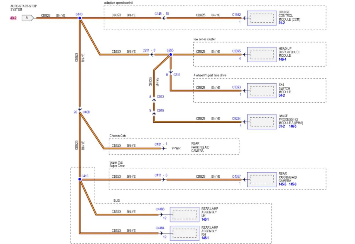
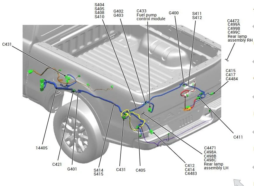
Awesome, sounds like a plan. I will get these checks done after work and report back.I see where the issue is: It explains all the latest voltage check results (lower and not equal with load applied) it also shows why the rear camera has (no voltage)
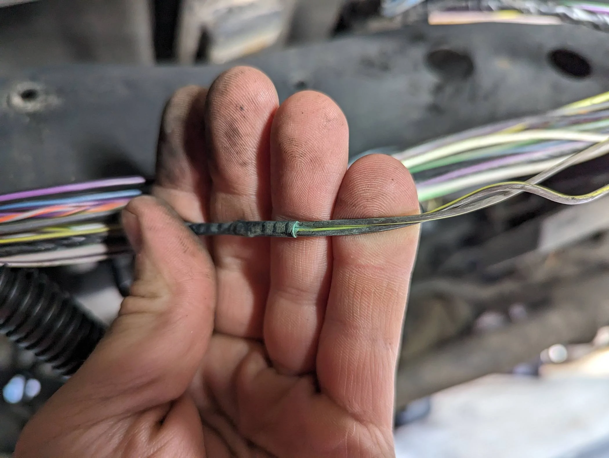
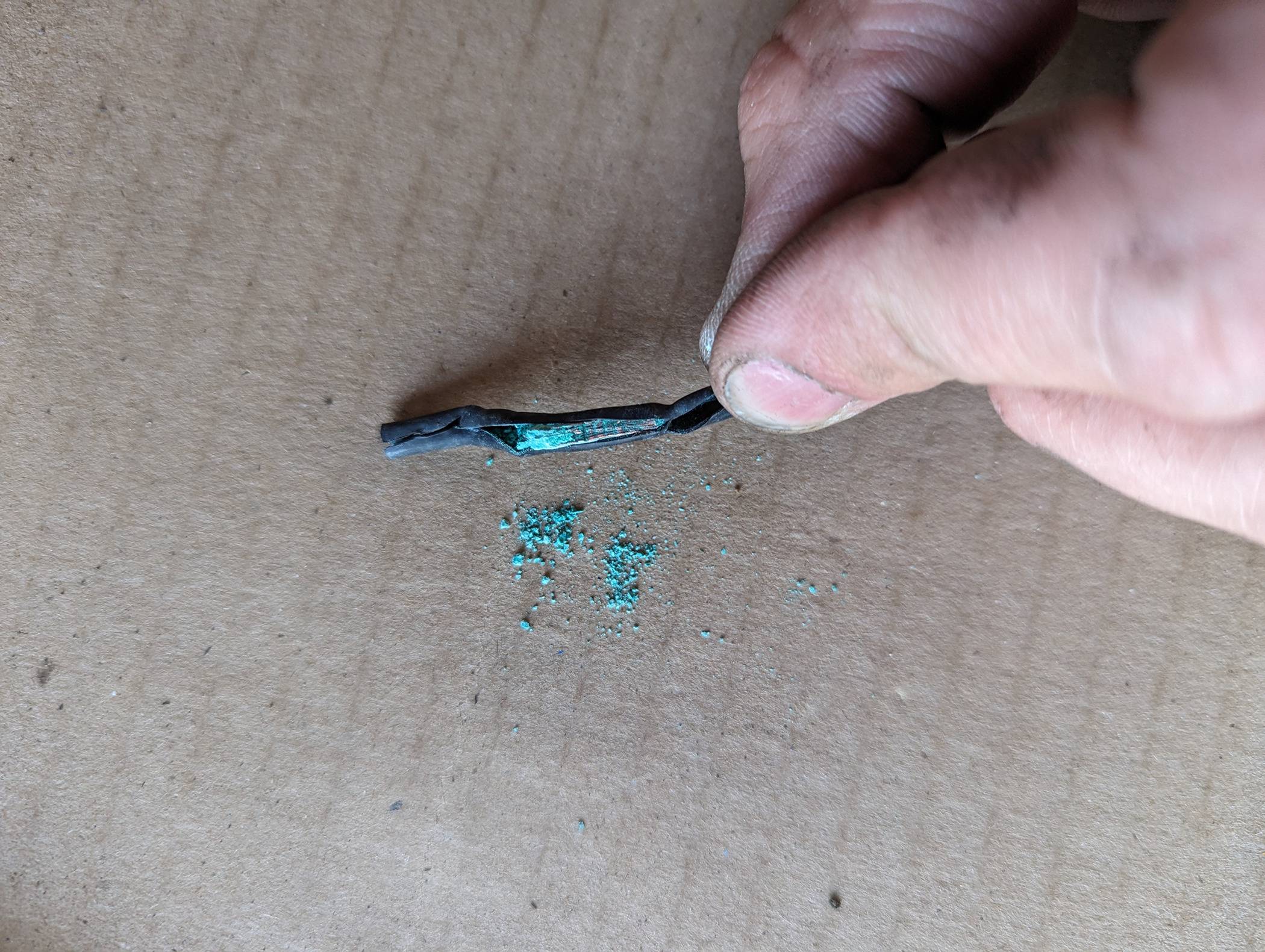
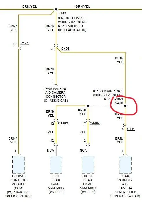
The Splice @ S410 is broken.
Note: For clarity (all 4 wires) are spliced together @ 1 point (ignore the dashed line)

Now to find it
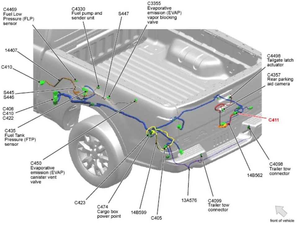
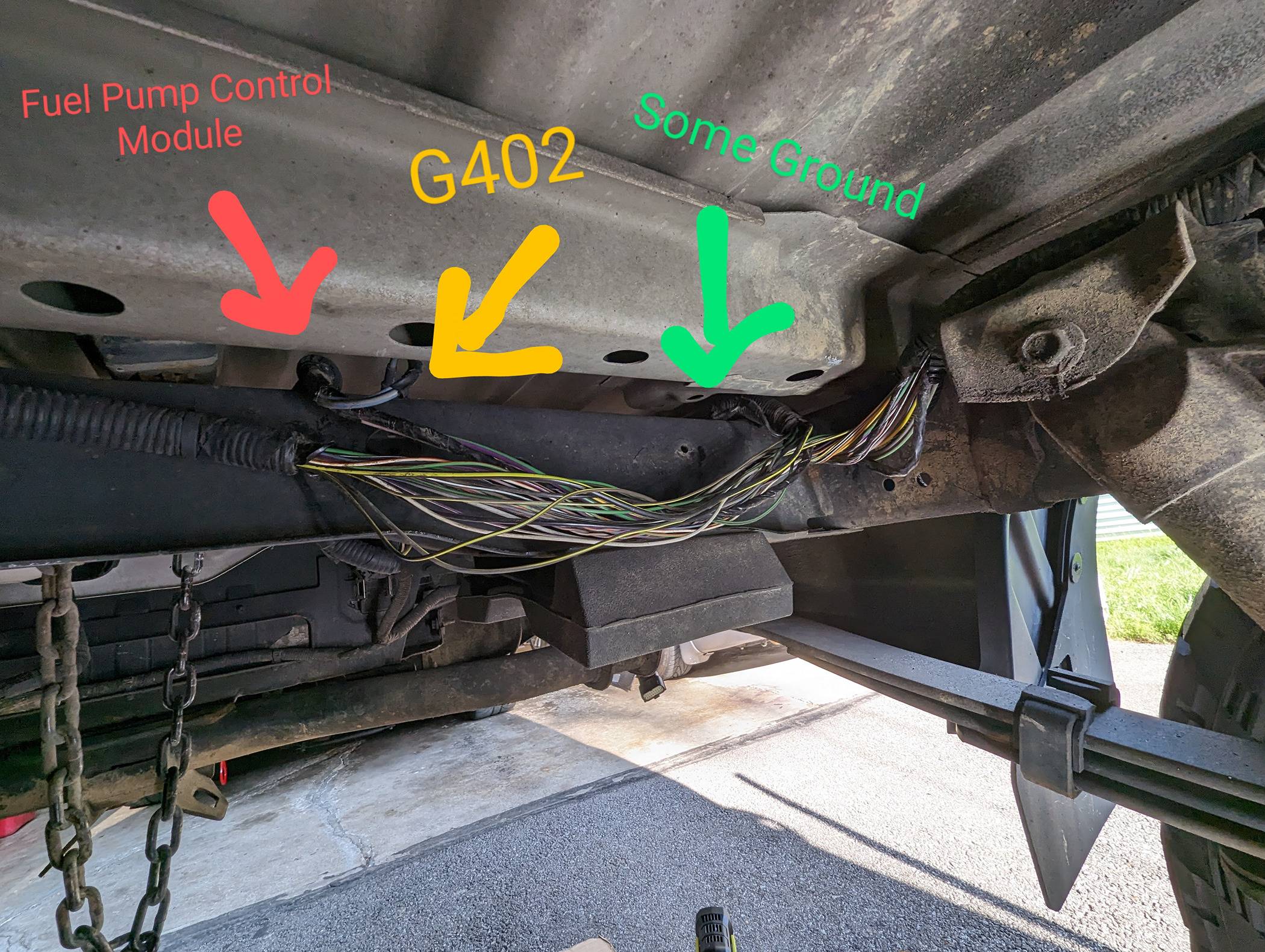
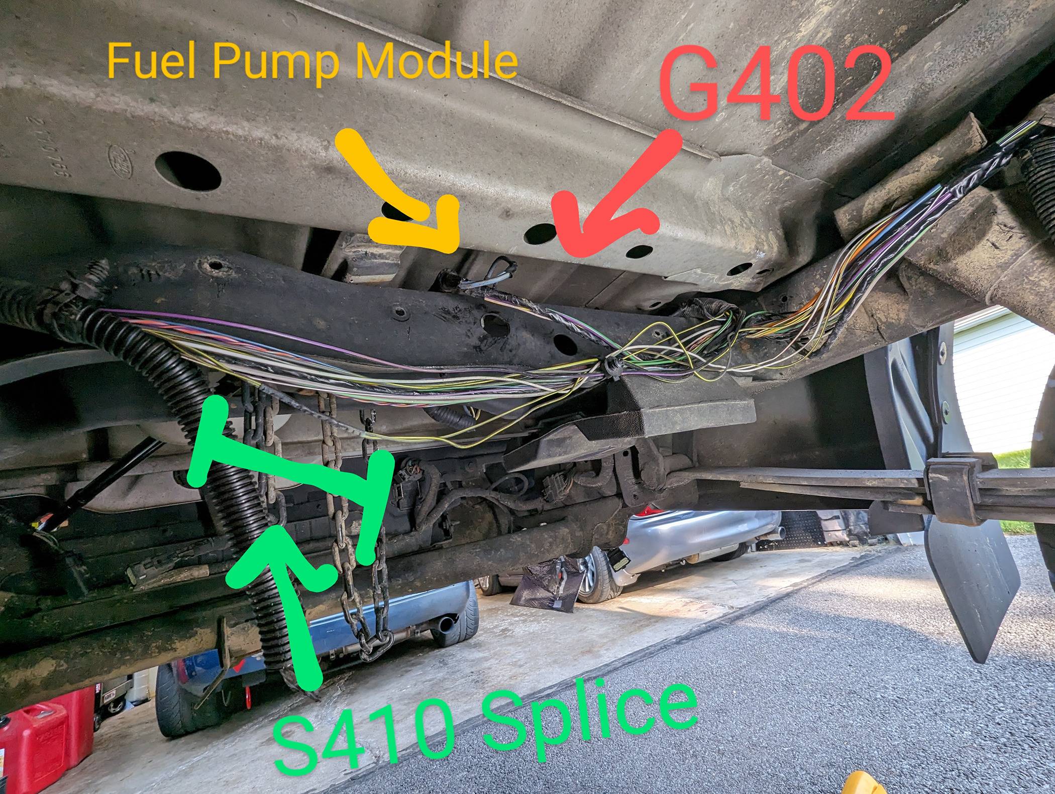
Location Description:
Rear Main Body Harness # 14405 - Near T/O (Take Off) to Ground Point G402
You will need to unwarp the harness to find it.

But to confirm before you pull apart the harness let's check some thighs first.
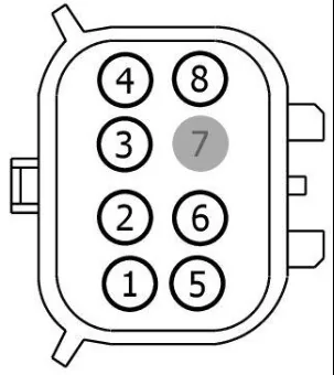
Find & Disconnect C411 - Connector
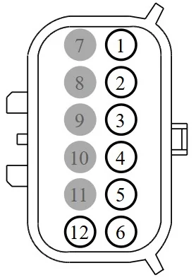
Do a check for power at Pin 6, same as above checks, does it match the readings that you had on the camera connector.
I want to eliminate the slight possibility that the camera leg from the splice being shorted to ground.

One last test if you want, just a secondary check for continuity
Disconnect C408 - C4483 - C4484 and C411 all at once
At C408 - (REARWARD) Connector - Jumper Pin #26 to Ground
Meter - Ohms Scale
At Connector:
C4483 - Pin #12 to Body Grd
C4484 -Pin #12 to Body Grd
C411 - Pin #6 to Body Grd
Shold be reading 3 ohms or less on all connectors, but I suspect you will get high resistance with C4483/C4484 and VERY High resistance on C411
So most likely a broken splice point but possible that between C411 and the Splice is a short to ground. My gut tells me it's the splice point. We have at least confirmed the problem lies between the rear camera connector and that splice point.
Sponsored