OP
OP
MiataBro11
Well-Known Member
- First Name
- Ethan
- Joined
- Feb 4, 2020
- Threads
- 2
- Messages
- 51
- Reaction score
- 20
- Location
- Cleveland, OH
- Vehicle(s)
- 2021 Tremor / 1994 Mazda Miata Racecar
- Occupation
- Research Lab Tech
- Thread starter
- #31
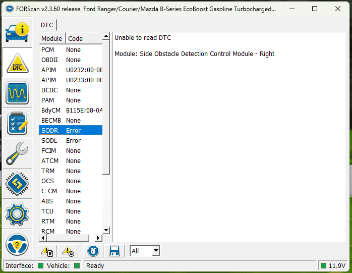
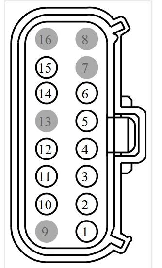
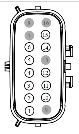
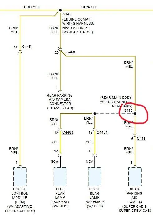
Yes I pulled the connector and it was clean and dry inside. Also what's weird to me is that the rear parking sensors work totally fine and they seem to be in the same harness as the BLIS/taillights and the backup cam.If your left-hand front and rear parking lamps work, you have power to the Body Control Module to power the license plate lights, as they are all powered from the "hot at all times" power feed.
If you don't have a bulb connected to provide a load to the wire that you are testing for voltage, the BCM might cut power to it, so you may not be able to measure a voltage. I am not sure of this though.
I was wondering if BLIS will work if the rear camera is not working. They may be tied together in the programming so all three (two BLIS modules and rear camera) have to function together. Again, I am not sure of this.
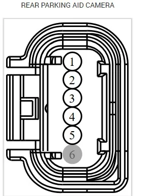
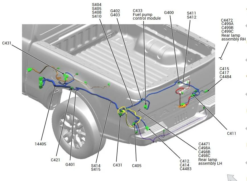
Have you checked the tail gate wiring plug for proper connection as this supplies connections to the rear camera.
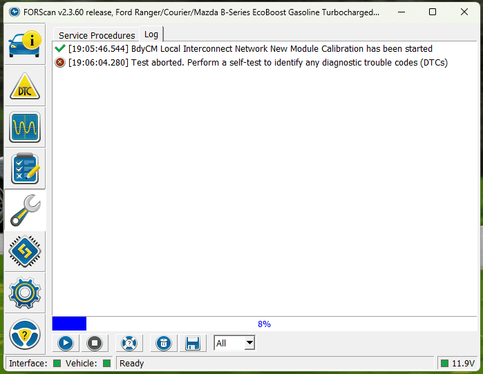
I also got my new camera in but that didn't make any difference. I know @airline tech said you had to do some sort of LIN module change (I think) with Forscan, but I didn't see any options related to the backup cam inside the BCM module config in Forscan.
Sponsored