
Sponsored

A/C not working

ControlNode

Well-Known Member
First Name
John
Joined
Nov 29, 2021
Threads
17
Messages
1,741
Reaction score
3,768
Location
Eastern NC
Vehicle(s)
84 Civic "2000S"/16 Focus RS/21 Ranger XLT
Occupation
Computers
Also, I thought I was including the following quote from the linked thread in my last reply where the OP there stated there was a dropped pin, which I'm guessing meant that the pin for the relay had pushed into the BJB when the relay was reinstalled.
Blower Fixed!!! Thank you to all that responded, the problem was a dropped pin in the BJB. I Replced the Box, with all relays and fuses for about 85.00. I will let everyone know what I find inside the bjb, I'm going to open the permanently sealed box and find out what went wrong, it's junk anyway, might as well learn something from it!!!!!
Sponsored


 
OP
OP

kevn

Member
First Name
Kevin
Joined
Jul 24, 2026
Threads
1
Messages
7
Reaction score
4
Location
84003
Vehicle(s)
2019 Ford ranger
Occupation
Technician
Pin 1 was getting 12.7v
Pin 3 getting 13.8v
Getting those numbers when using the chassis ground.

But not voltage between pin 1 & 2.

Look at the blower motor connector seems like it had an overload on the yellow/green wire, if not mistaken that's the 12 V going into the blower.

PXL_20260728_004437777.webp
 

airline tech

Well-Known Member
Joined
Aug 24, 2022
Threads
28
Messages
4,684
Reaction score
8,974
Location
Midwest - KS
Vehicle(s)
2022 Ranger Lariat-Super Crew, Cactus Gray
Occupation
Aircraft Tech
Pin 1 was getting 12.7v
Pin 3 getting 13.8v
Getting those numbers when using the chassis ground.

But not voltage between pin 1 & 2.

Look at the blower motor connector seems like it had an overload on the yellow/green wire, if not mistaken that's the 12 V going into the blower.

PXL_20260728_004437777.webp
Ok we have confirmed power at - the relay pin 3 , this eliminates the BJB as far as fuse to pin 3
You are not going to get any voltage from the FCIM to the coil as long as the code is present

We need to focus on the wire run from (Relay Pin 5)
For safety - do not jumper pin 3 to 5 - as we need to confirm that wire is not shorted.
I suspect that the contact in the (Blower) connector is just melted , but we need to confirm its only at this connector.

1. Remove the relay then go to the blower connector and measure (Pin 2 to Grd) Ohms Scale
We want to see (Open) or (OL)
This ensures the wire is not shorting to grd

2. Relay Removed & Blower Connector (Removed) - Jumper Relay Pin 5 to Grd, then go to Blower Connector and measure (Ohms scale) Pin 2 to Grd - expect high resistance, pull the connector apart and check the wire, the connector is verified damaged so need to replace it, so with the new connector you will need to cut back some wire for the splice anyway after this is cut or use a piercing test probe and move away from the connector and see if you get a better reading (lower resistance)

I suspect its just melted here (Pin 2) but its best to check wire integrity to be sure before forcing voltage down the wire
the above tests will do that and also note that since this contact is melted the contact or wire between relay pin 5 and blower pin 2 - may also be melted or damaged, this is what needs verified (not damaged) and the only damage is at this connector

Pigtail PN: WPT-1177

Pinout:
1- Not Used
2. Relay Power Feed
3. FCIM Control
4. Ground

C297 Pinout.webp
 

RangerBill

Well-Known Member
First Name
Bob
Joined
Jun 8, 2022
Threads
3
Messages
1,872
Reaction score
2,635
Location
PA
Vehicle(s)
2019 Ford Ranger Lariat Super Crew FX4
Occupation
retired
Pin 1 was getting 12.7v
Pin 3 getting 13.8v
Getting those numbers when using the chassis ground.

But not voltage between pin 1 & 2.

Look at the blower motor connector seems like it had an overload on the yellow/green wire, if not mistaken that's the 12 V going into the blower.

PXL_20260728_004437777.webp
Pin 2 and 3 of the relay should have 12 volts on them when the blower is supposed to be running. Pin 1 of the relay should read near zero ohms to ground. It should not have a voltage reading to chassis ground as you state.

With the relay removed, check to see if you have a good connection to ground at pin 1 of the relay. Using an ohmmeter, you should read close to zero ohms from relay pin 1 to a ground connection on the vehicle. The relay will not pick up without a good ground connection to relay pin 1. Make this measurement and report the results.

The melted connector contact at the blower was likely caused by a poor connector contact with the motor socket and the motor current caused it to heat up. It will need to be repaired or replaced.
 
Last edited:

airline tech

Well-Known Member
Joined
Aug 24, 2022
Threads
28
Messages
4,684
Reaction score
8,974
Location
Midwest - KS
Vehicle(s)
2022 Ranger Lariat-Super Crew, Cactus Gray
Occupation
Aircraft Tech
Yes - Pin 1 - Relay Coil to Ground is also a good check, but my point is - with that code logged in the FCIM - it may be disabling the power out to the coil, so if he is checking for power (pin 2 - relay) with that code logged - the FCIM may not be providing it
Do not get tripped up on the exact wording of the code - the coil circuit is open because it cannot close- the FCIM has logged a circuit issue - and the fail safe is to kill the relay coil power, this is the code - not specific to actually being on coil circuit.
Can it mislead - yes - but a confirmed issue was found on a high current power feed, this is where the focus needs to be - damaged connector and verify that wire and the relay pin itself are also not burned or melted - the only true way to test the wire between the FCIM and the BJB Relay is to pull the FCIM connector and or get access to this connector the 1/2 way point - this connector is slightly buried - i would only venture here and dig into the coil side if after the damaged connector is replaced and that wire feed is verified good, then it will down to either bad circuit (coil power) or FCIM internally fried - I think its a simple as replacing the module connector and all will be good - but want to verify that the high current wire feed is intact before throwing voltage on it - do not want to see a smoke event - let the FCIM do its job - its protecting the circuit and has shut down the power supply to the motor

C237 Detailed.webp


OP
OP

kevn

Member
First Name
Kevin
Joined
Jul 24, 2026
Threads
1
Messages
7
Reaction score
4
Location
84003
Vehicle(s)
2019 Ford ranger
Occupation
Technician
Sorry for the delayed, I had a busy August and most of September.

I removed the connector to the blower motor, as picture showed on previous threads, it looked in bad condition. I removed the connector and the actual wire looked fine, no signs of overload or shorting.
I got the new one I ordered installed it and it continued with the same issue.

After doing some digging, I decided to jumper the load side of the relay, to test of the blower motor would turn on. After jumpering out pin 3 and 5, the blower motor turned on. I noticed the compressor didn't engage. After doing some research I believe because of a interlock, due to a leak on the line or the evaporator temperature sensor was malfunctioning.

Using a scanner I ruled out the sensor, and I checked the pressure in the line on the Ac side, since the compressor wasn't kicking in I was not expecting to get a good reading when connecting the gauge, but it was worth the shot to see if there was some pressure. I connected the gauge and it read warning at max pressure, my only take away was that it was probably not leaking due to the static pressure.

So I had to come back to the battery junction box. Testing the control side on the sockets. I manually tested the relay I bought to te battery and it was working, could hear the relay switching. I checked voltage from socket 1 to chassis and I was getting 12 V, when having the AC on. Socket 2 to chassis was 0v and was also 0v to battery positive. The first reading of socket 2 to chassis is a "normal" reading due that, socket 2 is ground on the control side, so ground to chassis there should not be any difference in voltage, that why and when ahead and tested to the battery positive, reading came back to 0v. That didn't make sense.

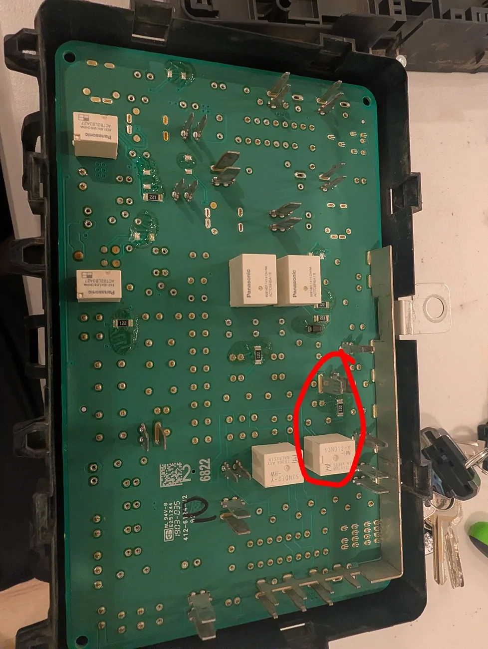
I removed the BJB, remove the fuses on the back side as well as the cover and was able to reach the backplane of the PCB. I ohms out the socket 2 to the backplane, it was reading 0.5 ohms, but after measuring how much resistance I had on my probes, by touching them, it was 0.4 ohms, I deducted it was 0.1 ohms, 0.5-0.4=0.1 ohms.

PXL_20260923_041724531~2.webp
 
OP
OP

kevn

Member
First Name
Kevin
Joined
Jul 24, 2026
Threads
1
Messages
7
Reaction score
4
Location
84003
Vehicle(s)
2019 Ford ranger
Occupation
Technician
Since I didn't wanted to remove the PCB form the top cover and end up not having a car, I decided to stop at that point. On the backplane of the PCB, socket 2 is connected to another relay. I marked it on my last reply.

Because I could feel the temp on the vents when it turned on the heater, I figured the continuity between the FCIM and the control module was good. I decided to ordered a BJB replacement from eBay, I got it for $50, I made sure it was the right one, since BJB between trim and 4x4 are different. I got the replacement on Saturday, I installed the BJB and AC started working. I'll try to open the old bjb and see what's wrong on socket 2.

Thanks for all the help.
 

airline tech

Well-Known Member
Joined
Aug 24, 2022
Threads
28
Messages
4,684
Reaction score
8,974
Location
Midwest - KS
Vehicle(s)
2022 Ranger Lariat-Super Crew, Cactus Gray
Occupation
Aircraft Tech
Ok - at least you have a verified fix
Now curiosity sets in for me - since this is the first pic I have seen of the internal BJB board and wonder - What these 6 relays are for - 3 separate part numbers?

I deduced that these 6 relays are:
Need to determine (relay) location ident - dig some into the placement to pinpoint what each one is for.

1. 4WD - Main Relay
2. Rear Window Defrost Relay
3. Transmission Relay
4. Power Point Relay #1
5. Power Point Relay #2
6. Run / Accessory Relay

The Run / Accessory relay - feeds the Wiper Motor and Rain Sensor so no tie to the blower motor itself - at least by the wiring diagrams

Did you have issues with the Wipers as well? In Accy or Run mode?

I think the BCM may have 6ea of these relays on the board for a total of 12 (non-serviceable) relays
 
Last edited:

airline tech

Well-Known Member
Joined
Aug 24, 2022
Threads
28
Messages
4,684
Reaction score
8,974
Location
Midwest - KS
Vehicle(s)
2022 Ranger Lariat-Super Crew, Cactus Gray
Occupation
Aircraft Tech
Thinking (Possibly)

2 × 53ND12-Y-HW (40 A) Rear Defrost + Run/Accessory Relay
2 × ACTC6F6A18 Power Point #1 + Power Point #2 Relay
2 × ACTB2LB3A27 4WD Main + Transmission Relay
Sponsored


Top