
Sponsored

Ford warns that Active Cruise Control can NOT be used with an aftermarket trailer brake controller

RangerBill

Well-Known Member
First Name
Bob
Joined
Jun 8, 2022
Threads
3
Messages
1,659
Reaction score
2,215
Location
PA
Vehicle(s)
2019 Ford Ranger Lariat Super Crew FX4
Occupation
retired
I wonder if the Rangers with the rear LED taillights brake light are also pulse width modulated to limit current through the LEDs. LEDs need to be supplied with current limited power, or they will burn out. This can be accomplished with a dropping resister (as with the LED cargo lamps) or by current limiting power to the LED (PWM signal). So, if you have LED taillights, you may not be able to use a connection to the LED taillight without conditioning it (through the Lumen module).

If someone has an oscilloscope, it could be seen it they are supplied with a PWM signal to limit current to the taillights, or LED CMHSL.

If you have a non-LED Ranger, then the Lumen module would likely not be needed.

This is all speculation.
Sponsored

 

airline tech

Well-Known Member
Joined
Aug 24, 2022
Threads
28
Messages
4,499
Reaction score
8,592
Location
Midwest - KS
Vehicle(s)
2022 Ranger Lariat-Super Crew, Cactus Gray
Occupation
Aircraft Tech
I wonder if the Rangers with the rear LED taillights brake light are also pulse width modulated to limit current through the LEDs. LEDs need to be supplied with current limited power, or they will burn out. This can be accomplished with a dropping resister (as with the LED cargo lamps) or by current limiting power to the LED (PWM signal). So, if you have LED taillights, you may not be able to use a connection to the LED taillight without conditioning it (through the Lumen module).

If someone has an oscilloscope, it could be seen it they are supplied with a PWM signal to limit current to the taillights, or LED CMHSL.

If you have a non-LED Ranger, then the Lumen module would likely not be needed.

This is all speculation.
I know that by my As-Built compare spreadsheet - All 5G Rangers have this setting to (3)
Now the Headlights setting for VRMS changes between Halogen & LED housings but it does not give you a setting like the Stop / Position does it lists it as Type

Headlights:

Frequency Select
726-26-02 - 0000-0002-0057 (Halo)
726-26-02 - 0000-0001-0056 (LED) xxxx-xxx1-xxxx
0-Type (0) LED - 1=Type 1 (LED) 2-Type 2 (Halo) 3= Type 3
Moves the DRL from Low Beam to (Dedicated DRL Ckt)
This automatically changes 726-50-01 to (108E) 10 = Dedicated DRL
When (Dedicated DRL) is selected it Powers Pn #6 at the Headlight assembly

VRMS Target Select Cfg
726-29-01 - 0000-0000-0259 (Halo)
726-29-01 0000-0000-0158 (LED) xxxx-xxxx-x1xx
0= Type (0) LED - 1=Type 1 (LED) 2=Type 2 (Halo) 3= Type 3
This ties to 726-26-02 (Power Output) and they need to match
Note: This does not autochange when the above 726-26-02 is changed

The above changes are only between the Halo Headlights & LED Headlights so these are specific to the Lariat Trim or if you upgrade them to LEDs, as these are the same settings between say an XL and XLT where one could have either Incandescent or LED Taillights and CHMSL.

The odd thing is - I do not see any Voltage Related As-Builts for the - Turn Signals and the Prevalent Hyper-Flash issues that some have when swapping in LED Bulbs for Turns, and since all have Incandescent bulbs in the front but the rear may have either, I would expect to see a setting for that. I believe its due to the voltage is (On/Off) and not a constant voltage that needs controlled.


Stop / Position Lights:

BCM- 726-26-01 xxxx-xxx3-xxxx - We are set to 3 - Control Stop & Position Configure
3=VRMS/VRMS
Options are: 0= Duty/Duty - 1= Duty/VRMS - 2=VRMS/Duty
So the BCM is using this to stabilize and regulate the voltage on the Brake Light Circuit.

No change in the As-Built files between the trims and this is the only As-Built setting for voltage.
 

RangerBill

Well-Known Member
First Name
Bob
Joined
Jun 8, 2022
Threads
3
Messages
1,659
Reaction score
2,215
Location
PA
Vehicle(s)
2019 Ford Ranger Lariat Super Crew FX4
Occupation
retired
I know that by my As-Built compare spreadsheet - All 5G Rangers have this setting to (3)
Now the Headlights setting for VRMS changes between Halogen & LED housings but it does not give you a setting like the Stop / Position does it lists it as Type

Headlights:

Frequency Select
726-26-02 - 0000-0002-0057 (Halo)
726-26-02 - 0000-0001-0056 (LED) xxxx-xxx1-xxxx
0-Type (0) LED - 1=Type 1 (LED) 2-Type 2 (Halo) 3= Type 3
Moves the DRL from Low Beam to (Dedicated DRL Ckt)
This automatically changes 726-50-01 to (108E) 10 = Dedicated DRL
When (Dedicated DRL) is selected it Powers Pn #6 at the Headlight assembly

VRMS Target Select Cfg
726-29-01 - 0000-0000-0259 (Halo)
726-29-01 0000-0000-0158 (LED) xxxx-xxxx-x1xx
0= Type (0) LED - 1=Type 1 (LED) 2=Type 2 (Halo) 3= Type 3
This ties to 726-26-02 (Power Output) and they need to match
Note: This does not autochange when the above 726-26-02 is changed

The above changes are only between the Halo Headlights & LED Headlights so these are specific to the Lariat Trim or if you upgrade them to LEDs, as these are the same settings between say an XL and XLT where one could have either Incandescent or LED Taillights and CHMSL.

The odd thing is - I do not see any Voltage Related As-Builts for the - Turn Signals and the Prevalent Hyper-Flash issues that some have when swapping in LED Bulbs for Turns, and since all have Incandescent bulbs in the front but the rear may have either, I would expect to see a setting for that. I believe its due to the voltage is (On/Off) and not a constant voltage that needs controlled.


Stop / Position Lights:

BCM- 726-26-01 xxxx-xxx3-xxxx - We are set to 3 - Control Stop & Position Configure
3=VRMS/VRMS
Options are: 0= Duty/Duty - 1= Duty/VRMS - 2=VRMS/Duty
So the BCM is using this to stabilize and regulate the voltage on the Brake Light Circuit.

No change in the As-Built files between the trims and this is the only As-Built setting for voltage.
I went out and measured the voltage to my LED stop light. It shows no AC voltage as would be with a PWM signal. I read 12.3 volts DC, so battery voltage is being applied to the LED stop light. The taillight assembly must have a built-in driver for the LED module.
 

airline tech

Well-Known Member
Joined
Aug 24, 2022
Threads
28
Messages
4,499
Reaction score
8,592
Location
Midwest - KS
Vehicle(s)
2022 Ranger Lariat-Super Crew, Cactus Gray
Occupation
Aircraft Tech
I went out and measured the voltage to my LED stop light. It shows no AC voltage as would be with a PWM signal. I read 12.3 volts DC, so battery voltage is being applied to the LED stop light. The taillight assembly must have a built-in driver for the LED module.
Was that with Engine Off or Engine Running?
I wish I knew the true answer, all I know is that the BCM (Internally) handles the voltage output and I would have to check for sure but I think that since the lighting system has (FET) the BCM has to have a way to determine circuit integrity - so the BCM is regulating the voltage output be it
PWM or RMS as its (circuit control factor) and with the As-Builts giving a setting for VRMS or Duty, I am going with its a (Pulsed DC) voltage noted as VRMS in the BCM programming, Duty Cycle - Generally is a reference to PWM (Voltage)
Other BCM Lighting settings list either a (Percentage) or (Duty Cycle)

As I have never tested the Brake Light circuit I am curious with the engine running - What the voltage reading would be on the Brake Light circuit?
I have a feeling its going to be a lower voltage than you would have at the battery a more steady 12 volts vs 13.7 - 14.7 or whatever the battery voltage is. however with a scope you would probably see the voltage pulsing slightly a meter would not pick it up.
 
Last edited:

RangerBill

Well-Known Member
First Name
Bob
Joined
Jun 8, 2022
Threads
3
Messages
1,659
Reaction score
2,215
Location
PA
Vehicle(s)
2019 Ford Ranger Lariat Super Crew FX4
Occupation
retired
Was that with Engine Off or Engine Running?
I wish I knew the true answer, all I know is that the BCM (Internally) handles the voltage output and I would have to check for sure but I think that since the lighting system has (FET) the BCM has to have a way to determine circuit integrity - so the BCM is regulating the voltage output be it
PWM or RMS as its (circuit control factor) and with the As-Builts giving a setting for VRMS or Duty, I am going with its a (Pulsed DC) voltage noted as VRMS in the BCM programming, Duty Cycle - Generally is a reference to PWM (Voltage)
Other BCM Lighting settings list either a (Percentage) or (Duty Cycle)

As I have never tested the Brake Light circuit I am curious with the engine running - What the voltage reading would be on the Brake Light circuit?
I have a feeling its going to be a lower voltage than you would have at the battery a more steady 12 volts vs 13.7 - 14.7 or whatever the battery voltage is. however with a scope you would probably see the voltage pulsing slightly a meter would not pick it up.
Engine was not running. I checked using the AC scale of a Fluke DVM and there was no AC component at all, so no PWM. If I have some time, I will test with the engine running.


RangerBill

Well-Known Member
First Name
Bob
Joined
Jun 8, 2022
Threads
3
Messages
1,659
Reaction score
2,215
Location
PA
Vehicle(s)
2019 Ford Ranger Lariat Super Crew FX4
Occupation
retired
Was that with Engine Off or Engine Running?
I wish I knew the true answer, all I know is that the BCM (Internally) handles the voltage output and I would have to check for sure but I think that since the lighting system has (FET) the BCM has to have a way to determine circuit integrity - so the BCM is regulating the voltage output be it
PWM or RMS as its (circuit control factor) and with the As-Builts giving a setting for VRMS or Duty, I am going with its a (Pulsed DC) voltage noted as VRMS in the BCM programming, Duty Cycle - Generally is a reference to PWM (Voltage)
Other BCM Lighting settings list either a (Percentage) or (Duty Cycle)

As I have never tested the Brake Light circuit I am curious with the engine running - What the voltage reading would be on the Brake Light circuit?
I have a feeling its going to be a lower voltage than you would have at the battery a more steady 12 volts vs 13.7 - 14.7 or whatever the battery voltage is. however with a scope you would probably see the voltage pulsing slightly a meter would not pick it up.
Ok, I redid the test with the engine running. There was 14.6 volts DC on the taillight stop lamp wire and no AC component showing on the AC scale (actually 20 millivolts). With the engine off, I read 12.5 volts DC. Both readings were about .1 volt DC lower than battery voltage.

I also checked the CMHSL stop lamp circuit with the engine running I measured 14.6 volts DC and no AC component. I also noticed that this lamp assembly has LED driver components on its circuit board.

So, it looks like there is no PWM signal to either taillight or CHMSL stop lights, only switched battery voltage.
 

airline tech

Well-Known Member
Joined
Aug 24, 2022
Threads
28
Messages
4,499
Reaction score
8,592
Location
Midwest - KS
Vehicle(s)
2022 Ranger Lariat-Super Crew, Cactus Gray
Occupation
Aircraft Tech
Its not going to be AC, its still a DC Voltage, so the BCM is not limiting the voltage and its still a varying voltage the only way to see the (difference) between the 2 inputs would be to view the signals on a (Lab Scope)
The signal needs to be viewed on a scope that can pick up a faster signaling rate that the meter cannot pick up.
I will be honest, I have never really learned how to use one proficiently and have never owned one until recently with my newer Snap-On scanner with scope - as I have always gotten by with a simple meter and never really had the need for one since I do not do automotive professionally anymore, although I have used them on occasion in my career its not been enough to say I am proficient with them.

I know the basics of the setup and that the (waveform) is more precise.
It is on my list of something I would like to get more comfortable in using, it is a great T-Shoot tool but sometimes the extra work involved to back probe the connectors for the signal vs reading the Live Data PID of the signal (On/Off - Active/Inactive - True/False) makes this a tool that most technicians rarely use.

So I will have to get my scope out and actually hook into both signals so we can compare the 2.
I truly suspect the BCM (Output) to be pulsing to a small degree.
This can be viewed as switching on the waveform.
So if I get the time to do it, it will be a learning experience for myself as well as this forum.


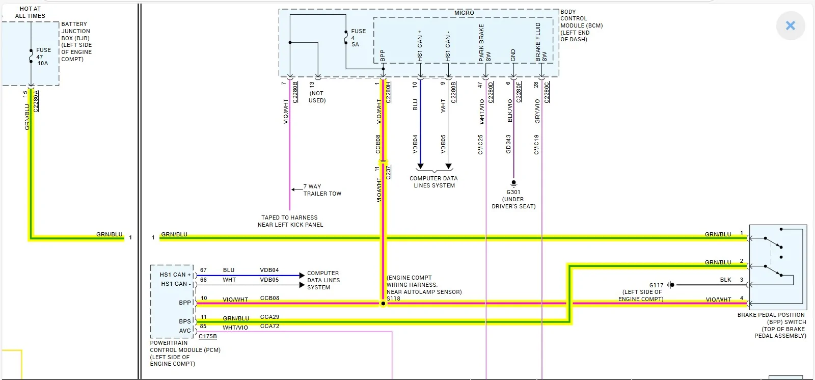
The output of the Brake Switch (BPP) signal is going to be more of a constant voltage - when viewed on a scope as this voltage is direct off of the (BJB) fused feed - it will be more of a straight line however increasing or decreasing with the battery voltage.

So the plan is to - back probe 3 total signals to compare:

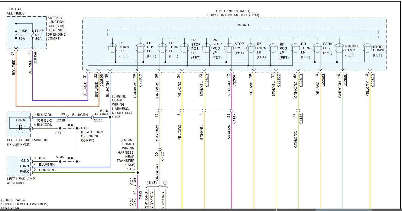
The BPP - CHMSL and Brake Light, since the BCM has the CHMSL on a separate circuit, I want to see if the waveform is different and may show the reason Lumen taps to that vs Brake Lights.
as this is the only true way to find an answer and what will the testing show.
Same or Different waveforms.
I have a hunch I am going to see a difference between the BJB and BCM outputs, not sure between the CHMSL & Brake light - I think they will be the same.

For a Ref:
What is not shown here - it takes a Can Bus signal to provide the output power to the circuit
These would be Stop Lamps and Stop CHMSL.
So it boils down to - how does the internal circuitry of the BCM control the power output through the (FET) Field Effect Transistor
I know the basics of the (FET) protection - Control & Monitor the output, but what does the actual voltage output look like in a waveform?
We know that the BCM is very finicky with outputs when others have added lighting etc, this is the reason why - the FET protection that is programed into the BCM and the unknown is:
What is the Min/Max allowance variable (of Current)before it triggers a fault or flicker/flash issue?

Lights Output.jpeg


and this
1754697606923-p4.webp
 

RangerBill

Well-Known Member
First Name
Bob
Joined
Jun 8, 2022
Threads
3
Messages
1,659
Reaction score
2,215
Location
PA
Vehicle(s)
2019 Ford Ranger Lariat Super Crew FX4
Occupation
retired
[/QUOTE]
Its not going to be AC, its still a DC Voltage, so the BCM is not limiting the voltage and its still a varying voltage the only way to see the (difference) between the 2 inputs would be to view the signals on a (Lab Scope)
The signal needs to be viewed on a scope that can pick up a faster signaling rate that the meter cannot pick up.
I will be honest, I have never really learned how to use one proficiently and have never owned one until recently with my newer Snap-On scanner with scope - as I have always gotten by with a simple meter and never really had the need for one since I do not do automotive professionally anymore, although I have used them on occasion in my career its not been enough to say I am proficient with them.

I know the basics of the setup and that the (waveform) is more precise.
It is on my list of something I would like to get more comfortable in using, it is a great T-Shoot tool but sometimes the extra work involved to back probe the connectors for the signal vs reading the Live Data PID of the signal (On/Off - Active/Inactive - True/False) makes this a tool that most technicians rarely use.

So I will have to get my scope out and actually hook into both signals so we can compare the 2.
I truly suspect the BCM (Output) to be pulsing to a small degree.
This can be viewed as switching on the waveform.
So if I get the time to do it, it will be a learning experience for myself as well as this forum.


The output of the Brake Switch (BPP) signal is going to be more of a constant voltage - when viewed on a scope as this voltage is direct off of the (BJB) fused feed - it will be more of a straight line however increasing or decreasing with the battery voltage.

So the plan is to - back probe 3 total signals to compare:

The BPP - CHMSL and Brake Light, since the BCM has the CHMSL on a separate circuit, I want to see if the waveform is different and may show the reason Lumen taps to that vs Brake Lights.
as this is the only true way to find an answer and what will the testing show.
Same or Different waveforms.
I have a hunch I am going to see a difference between the BJB and BCM outputs, not sure between the CHMSL & Brake light - I think they will be the same.

For a Ref:
What is not shown here - it takes a Can Bus signal to provide the output power to the circuit
These would be Stop Lamps and Stop CHMSL.
So it boils down to - how does the internal circuitry of the BCM control the power output through the (FET) Field Effect Transistor
I know the basics of the (FET) protection - Control & Monitor the output, but what does the actual voltage output look like in a waveform?
We know that the BCM is very finicky with outputs when others have added lighting etc, this is the reason why - the FET protection that is programed into the BCM and the unknown is:
What is the Min/Max allowance variable (of Current)before it triggers a fault or flicker/flash issue?

Lights Output.webp


and this
1754697606923-p4.webp
If the voltage is being pulsed, it would register on a DVM on the AC scale. I saw 20 mv which is ambient noise being induced into the test leads. On the DC scale, it would show as a reduced DC voltage level if PWM. (edited)

I no longer have access to an oscilloscope to test, but the AC scale would show any pulsed DC voltage (PWM) as an AC voltage component. The FET is being used as an electronic switch, on or off.
 
Last edited:

airline tech

Well-Known Member
Joined
Aug 24, 2022
Threads
28
Messages
4,499
Reaction score
8,592
Location
Midwest - KS
Vehicle(s)
2022 Ranger Lariat-Super Crew, Cactus Gray
Occupation
Aircraft Tech
Ok, as I said - I need to dig into how to truly use the Lab Scope
I could have used 2 signals on each (Screenshot) but was planning initially on picking up the (Light-Outputs) at the lights themselves but then decided on using the BCM Outputs for the lights instead.

I could not figure out how to (Zoom) in on the signal but did get the (timeline) down to 10ms and 5ms as well - did not have the instruction manual in the garage with me - :question: to get tighter views, so I need more self training on its use.
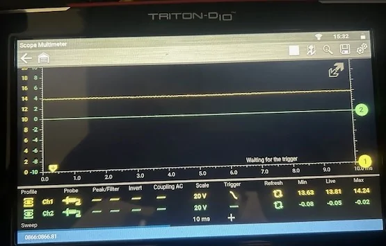
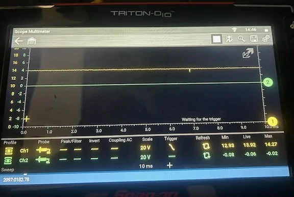
But I did pull out the information that I wanted from this little trial use.

Notes: for tapping points:

BPP Output - Direct off of the Violet/White wire that is in the (4-Wire) tapped set, this is the voltage input signal to the TBC that the Brake Pedal is pressed.

CHMSL Output - Probe Tapped into BCM Connector C2280D - Pin #13 Yellow/Grey, this is a direct feed to the CHMSL

Stop Lamp Output - Probed Tapped into BCM Connector C2280F - Pin #12 - Violet/Brown, this is a direct feed to both Left/Right Brake Lights.

I wish I could have figured out how to get a (Zoomed) waveform but if you look at the: (Min-Max) voltages in these shots - tells me the information I was wanting to know.
All of these shots were taken when the brake was applied and the waveform (refreshed) and the engine is idling.

BPP (Brake Pedal Position) Output
So this is following actual battery voltage and you see the charging variation of (0.61v)
I had my (Voltmeter) plugged in to the Power-point) as well and the voltage matched the Live Voltage.

BPP Signal.jpg


CHMSL Output:
Note the variance in the (Min/Max) and when you watch the waveform (live) you can see some voltage fluctuation as this is a load and lighting the LEDs, but I do not see a (Switching) or pulsing waveform like I thought I would see, I even dropped down to 5ms here and did not see what I think should be more or a Square Wave

CHMSL Signal.jpg


Stop / Brake Lights Output (Taillights)
Same signal as the CHMSL

Brake Lights (Taillamps).jpg


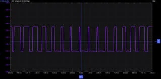
Online Example of a Sample PWM Waveform that I though I would see for reference.

PWM Example.jpg


So I conclude the reason for the Lumen Module is due to the fact that the (TBC) input is strictly a battery voltage input and not tied into (FET) protected circuit with a Transistor being part of the reason and the other is the voltage variation due to the (Output) load & (FET)
Although it is a small variance of voltage:
With This Test: (Difference between Min/Max)
BPP: (0.61v)
CHMSL: (1.34v)
Brake Taillights: (1.42v)

I believe the voltage variance is the (FET) momentarily switching the voltage Off/On, so yes I think the voltage is switching, its just not as a fast rate like PWM would.
The FET is controlling the voltage output similar to PWM but its simply turning off the current momentary to obtain an average voltage.

So since it has been reported that one of the reasons for the Lumen Module was to clean up the the voltage signal - I believe this is the reason that voltage variance coming out of the BCM and I THINK since this was a Ranger Specific issue (If I understand it correctly) rather than redesign a new TBC strictly for the Ranger they partnered with Lumen to provide the extra add-on module to let that varying voltage be used as the input to the TBC and the internal circuitry of the Lumen Module provides the same +/- Variance the TBC would see using the Violet/White wire.

In closing I cannot confirm its not a fast switching waveform until I gain some more use of the scope and actually get it on a known PWM circuit such as the Blower Motor as an example to have a real example of what I should see, all I have now is I have confirmed that there is a voltage variance between the 2 input sources to the TBC and I believe the FET is what is generating that variance.

And I think the FET is just simply a voltage regulator in the circuit that has the ability to turn the voltage off and on and the circuit is NOT PWM controlled, while it is common for PWM and FET (MOSFET) to be combined in a circuit, I do not think that is the case here.
Now I think that the Background Lighting, Ambient Lighting etc anything dimmable would have PWM and FET.
When it reaches the point it cannot control the circuit - it disables the circuit output.
At this point till proven wrong that's my theory.
 
Last edited:

RangerBill

Well-Known Member
First Name
Bob
Joined
Jun 8, 2022
Threads
3
Messages
1,659
Reaction score
2,215
Location
PA
Vehicle(s)
2019 Ford Ranger Lariat Super Crew FX4
Occupation
retired
Ok, as I said - I need to dig into how to truly use the Lab Scope
I could have used 2 signals on each (Screenshot) but was planning initially on picking up the (Light-Outputs) at the lights themselves but then decided on using the BCM Outputs for the lights instead.

I could not figure out how to (Zoom) in on the signal but did get the (timeline) down to 10ms and 5ms as well - did not have the instruction manual in the garage with me - :question: to get tighter views, so I need more self training on its use.
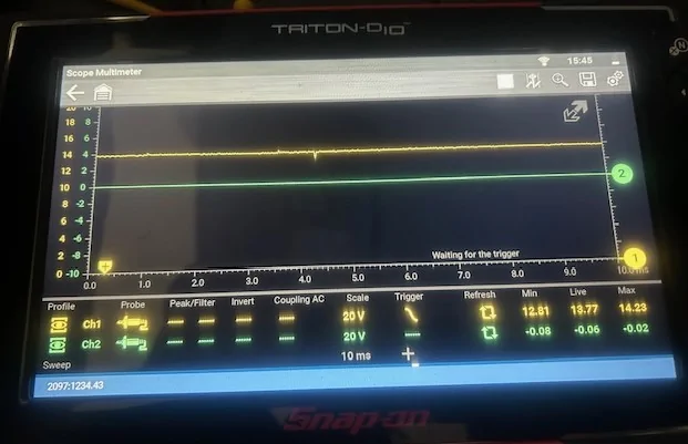
But I did pull out the information that I wanted from this little trial use.

Notes: for tapping points:

BPP Output - Direct off of the Violet/White wire that is in the (4-Wire) tapped set, this is the voltage input signal to the TBC that the Brake Pedal is pressed.

CHMSL Output - Probe Tapped into BCM Connector C2280D - Pin #13 Yellow/Grey, this is a direct feed to the CHMSL

Stop Lamp Output - Probed Tapped into BCM Connector C2280F - Pin #12 - Violet/Brown, this is a direct feed to both Left/Right Brake Lights.

I wish I could have figured out how to get a (Zoomed) waveform but if you look at the: (Min-Max) voltages in these shots - tells me the information I was wanting to know.
All of these shots were taken when the brake was applied and the waveform (refreshed) and the engine is idling.

BPP (Brake Pedal Position) Output
So this is following actual battery voltage and you see the charging variation of (0.61v)
I had my (Voltmeter) plugged in to the Power-point) as well and the voltage matched the Live Voltage.

BPP Signal.jpg


CHMSL Output:
Note the variance in the (Min/Max) and when you watch the waveform (live) you can see some voltage fluctuation as this is a load and lighting the LEDs, but I do not see a (Switching) or pulsing waveform like I thought I would see, I even dropped down to 5ms here and did not see what I think should be more or a Square Wave

CHMSL Signal.jpg


Stop / Brake Lights Output (Taillights)
Same signal as the CHMSL

Brake Lights (Taillamps).jpg


Online Example of a Sample PWM Waveform that I though I would see for reference.

PWM Example.jpg


So I conclude the reason for the Lumen Module is due to the fact that the (TBC) input is strictly a battery voltage input and not tied into (FET) protected circuit with a Transistor being part of the reason and the other is the voltage variation due to the (Output) load & (FET)
Although it is a small variance of voltage:
With This Test: (Difference between Min/Max)
BPP: (0.61v)
CHMSL: (1.34v)
Brake Taillights: (1.42v)

I believe the voltage variance is the (FET) momentarily switching the voltage Off/On, so yes I think the voltage is switching, its just not as a fast rate like PWM would.
The FET is controlling the voltage output similar to PWM but its simply turning off the current momentary to obtain an average voltage.

So since it has been reported that one of the reasons for the Lumen Module was to clean up the the voltage signal - I believe this is the reason that voltage variance coming out of the BCM and I THINK since this was a Ranger Specific issue (If I understand it correctly) rather than redesign a new TBC strictly for the Ranger they partnered with Lumen to provide the extra add-on module to let that varying voltage be used as the input to the TBC and the internal circuitry of the Lumen Module provides the same +/- Variance the TBC would see using the Violet/White wire.

In closing I cannot confirm its not a fast switching waveform until I gain some more use of the scope and actually get it on a known PWM circuit such as the Blower Motor as an example to have a real example of what I should see, all I have now is I have confirmed that there is a voltage variance between the 2 input sources to the TBC and I believe the FET is what is generating that variance.

And I think the FET is just simply a voltage regulator in the circuit that has the ability to turn the voltage off and on and the circuit is NOT PWM controlled, while it is common for PWM and FET (MOSFET) to be combined in a circuit, I do not think that is the case here.
Now I think that the Background Lighting, Ambient Lighting etc anything dimmable would have PWM and FET.
When it reaches the point it cannot control the circuit - it disables the circuit output.
At this point till proven wrong that's my theory.
I believe that the FET circuit to the CHMSL stop light is just an on or off electronic switch as I stated above, (and confirmed with my DVM and your scope) but I wonder if during an emergency braking event, if the stop lamps are flashed by the BCM to alert the following cars of the fast stop. If flashing stop lamps is true, then the Lumen ECM would filter this flashing signal to a steady output to the Redarc brake controller, so it doesn't pulse the trailer brakes. Just a guess as to why a Lumen module is needed at all to interface between the CHMSL stop signal and the Redarc controller.

FET circuits can switch a clean on or off battery voltage without any PWM, and our measurements are confirming that. Other circuitry in the BCM is monitoring the current flow through the FET (could be through sensing the voltage drop across a series resistor or other electronic current detection circuitry) and turn off the FET output if a high current is detected. This current monitoring circuit could also be used to detect a defective bulb or LED (abnormally low current detected) and give the driver a warning of the problem.
 

RangerBill

Well-Known Member
First Name
Bob
Joined
Jun 8, 2022
Threads
3
Messages
1,659
Reaction score
2,215
Location
PA
Vehicle(s)
2019 Ford Ranger Lariat Super Crew FX4
Occupation
retired
I believe the voltage variance is the (FET) momentarily switching the voltage Off/On, so yes I think the voltage is switching, its just not as a fast rate like PWM would.
The FET is controlling the voltage output similar to PWM but its simply turning off the current momentary to obtain an average voltage.
If it were doing this the scope would have shown it on the waveform. Even though FETs are capable of being switched on and off momentarily, they can also be used to produce a pure DC voltage output. Our measurements are showing it being used as a pure on/off switch (just like a relay). Ford is using these FETs as solid-state switches instead of using relays.
 

RangerBill

Well-Known Member
First Name
Bob
Joined
Jun 8, 2022
Threads
3
Messages
1,659
Reaction score
2,215
Location
PA
Vehicle(s)
2019 Ford Ranger Lariat Super Crew FX4
Occupation
retired
And I think the FET is just simply a voltage regulator
If this were true, then the stop lamp and CHMSL lamps voltage that I measured with engine running and not running would be the same. My readings were very close to battery voltage (14.6 volts engine running, and 12.5 volts not running). So, the FETs do not appear to be used in any kind of voltage regulator configuration.
 

airline tech

Well-Known Member
Joined
Aug 24, 2022
Threads
28
Messages
4,499
Reaction score
8,592
Location
Midwest - KS
Vehicle(s)
2022 Ranger Lariat-Super Crew, Cactus Gray
Occupation
Aircraft Tech
On the other side of the coin, we need to also factor in that they need to tap off of the Brake Light circuit for the input.
This adds a Power & Ground to the circuit that the FET is monitoring (Can Bus) sees this and can possibly trigger faults as its out of its monitoring OEM specs.
The Lumen Module may be only needed to allow (Error Free) tie in that the TBC cannot do.
Thinking along the same lines as adding (LED) lighting to Turns etc, if you do not use the ones marketed as (Can-Bus) error free - you have issues.

Yes, with a meter you will only see what the output voltage is, but it will not pick up a quick drop out of the voltage - the meter is not fast enough to refresh the signal.
I can at least verify a noted difference between the 2 inputs and a variance in voltage @ 10ms scale.
Note: The Brake pedal was manually pressed with a prybar wedged between the seat and the pedal for that test. So the pedal was not being moved in any way that would affect the voltage outputs.

So, I agree that we do not have a major (noted) difference in the voltage outputs and thinking about the FET as a monitoring device that can kill the circuit, its leaning towards the reason for the Lumen Module is the (FET) monitoring of the circuit the Lumen Module is basically Can Bus Error Free and the FET does not see a (out of threshold) flow and I believe Ford (tested) this and noted that the TBC created faults - There had to be some testing done before they decided they needed the Lumen Module.
In any case the FET in that circuit is a KEY FACTOR in this issue, and I may be wrong on the FET actually turning Off/On without the PWM signal as it looks now to be a simple switch, if it sees a out of range (current) it turns (OFF) until it sees a normal output, if it continues to see out of normal range it permanently kills the output - thus needing repair of the circuit and a code reset.

What that MIN/Max factor is for the output - IDK
 

RangerBill

Well-Known Member
First Name
Bob
Joined
Jun 8, 2022
Threads
3
Messages
1,659
Reaction score
2,215
Location
PA
Vehicle(s)
2019 Ford Ranger Lariat Super Crew FX4
Occupation
retired
An FET alone cannot monitor current or voltage. There has to be other additional circuitry monitoring current flow through the FET to the LED or incandescent lamps. The Ford wiring diagrams greatly simplify the circuits and leave out the current sensing part of the circuitry. A FET is a type of transistor where the gate is highly isolated from the drain and source parts of the FET. The gate also requires very low power to gate the FET on. MOSFETs are capable of switching higher currents with very little gate current because of the field effect coupling to the drain/source components of the device.
 

airline tech

Well-Known Member
Joined
Aug 24, 2022
Threads
28
Messages
4,499
Reaction score
8,592
Location
Midwest - KS
Vehicle(s)
2022 Ranger Lariat-Super Crew, Cactus Gray
Occupation
Aircraft Tech
Possibly using this - which is not shown the the wiring diagrams

A common application is in current sensing circuits. A small resistor (sense resistor) is placed in series with the source of the FET, and the voltage drop across this resistor is measured. Since the current through the resistor is controlled by the gate voltage, this voltage drop is proportional to the current flowing through the FET. This voltage can then be used to monitor the current or to trigger an overcurrent protection mechanism.
Sponsored


Top