Sponsored

Adding Adaptive Cruise Control?

5G Dan-O

Well-Known Member
First Name
Dan
Joined
Nov 20, 2021
Threads
10
Messages
216
Reaction score
280
Location
Morrisville, NY
Vehicle(s)
2020 Ranger
Occupation
Ford ASSET Instructor - Program Director
Well after much work on this front the factory wiring harness (listed previously) has no connections, Power, Ground or CAN BUS @ the connector C145.
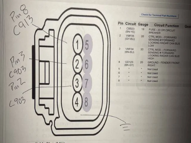
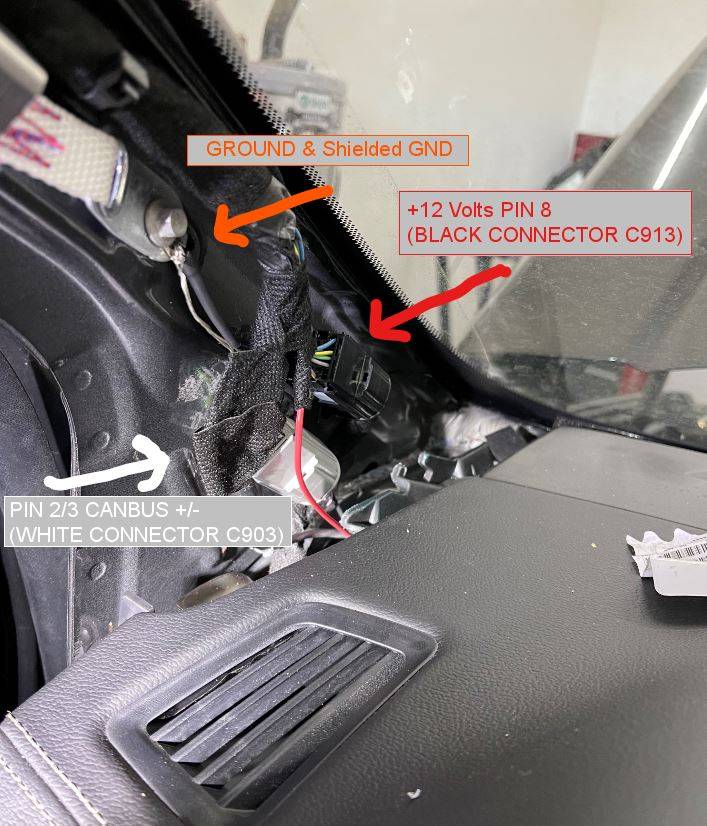
Oh no, I think that was covered a few pages back - that's why I just made my own harness from the pigtail of the sensor.
Sponsored


daczone

Well-Known Member
First Name
Dave
Joined
Dec 22, 2020
Threads
34
Messages
404
Reaction score
646
Location
Oregon
Vehicle(s)
2020 Ranger
Dave I have that mapped out!
Let me wake up a bit and I will post.
Here is what I have so far - I ran the wires but have not made the connection at the C903/C913. The Can bus goes to 1 of the connectors and the pwr goes to the other. I made the ground connection in front of the battery. And I went thru the fire wall thru the main harness grommet under the master cylinder.
Ping me if you need more info and good luck!
Okay going to wire this up and connect it. THANK YOU for the pin outs.
IMG_E3707 (Small).webp
 

daczone

Well-Known Member
First Name
Dave
Joined
Dec 22, 2020
Threads
34
Messages
404
Reaction score
646
Location
Oregon
Vehicle(s)
2020 Ranger
Okay going to wire this up and connect it. THANK YOU for the pin outs.
IMG_E3707 (Small).JPG

Got it wired up... checked and double checked my wires. They are good. I now have 12v at the radar unit but it never shows up as a module in my scan.

Maybe I have a bad unit?

  • Pin 2 on C903 (White Connector @ Drivers A pillar) is CANBUS + [my white wire which goes to pin 3 on C1582 (Radar Unit)]
  • Pin 3 on C903 (White Connector @ Drivers A pillar) is CANBUS - [my black wire which goes to pin 2 on C1582 (Radar Unit)]
  • Pin 8 on C913 (Black Connector @ Drivers A pillar) is +12 [my red wire which goes to pin 1 on C1582 (Radar Unit)]
  • GND is on a Drivers A pillar bolt. which goes to pin 4 on C1582 (Radar Unit)]
Canbus wires are twisted pair with a grounded shield (it was all I had). Ground is run separately to the a pillar bolt (you can see in the bottom picture with the black ground wire). Resistance measured at 0.6 ohms end to end, which compares to the factory harness.

IMG_3717.webp


wiring.JPG

Wrapped all back up with fabric tape.
 

micl9

Well-Known Member
First Name
Mike
Joined
Dec 21, 2019
Threads
31
Messages
1,368
Reaction score
1,949
Location
Apex, NC
Vehicle(s)
2019 Ranger XLT Fx4 302A
Vehicle Showcase
1
Did you create a new profile?
If I have time I will try to wire mine up tomorrow
 

5G Dan-O

Well-Known Member
First Name
Dan
Joined
Nov 20, 2021
Threads
10
Messages
216
Reaction score
280
Location
Morrisville, NY
Vehicle(s)
2020 Ranger
Occupation
Ford ASSET Instructor - Program Director
All right, so we're neck in neck in this horserace. :)

Sensor is installed, wiring pulled/run, LH steering wheel switch pack installed.
I also need to hook up the wires at the A-Pillar.

Had to stop at 5:30 - had friends coming over to go out to dinner.
I'm still foggy on how to set the PCM parameters.


daczone

Well-Known Member
First Name
Dave
Joined
Dec 22, 2020
Threads
34
Messages
404
Reaction score
646
Location
Oregon
Vehicle(s)
2020 Ranger
I got it!! Many thanks to CHrisin for getting me to look in the right direction.

My CANBUS signals were not on pins 2 and 3 as the diagrams show. I googled what CANBUS signals looks like (+ one is a data signal of 2.5 v) and the (- one is a data signal of about 2 volts). I got out my oscilloscope and found them. They were indeed at the white connector C903, but at the far side of the connector (2 wires) all alone. I plugged in my CCM and bam, Forscan found it!

Now to put my truck back together and begin testing!
 

micl9

Well-Known Member
First Name
Mike
Joined
Dec 21, 2019
Threads
31
Messages
1,368
Reaction score
1,949
Location
Apex, NC
Vehicle(s)
2019 Ranger XLT Fx4 302A
Vehicle Showcase
1
Glad you got it sorted!
So the wire diagrams didn't match!?
Did the wire color match?
 

daczone

Well-Known Member
First Name
Dave
Joined
Dec 22, 2020
Threads
34
Messages
404
Reaction score
646
Location
Oregon
Vehicle(s)
2020 Ranger
Glad you got it sorted!
So the wire diagrams didn't match!?
Did the wire color match?
My truck is a 2020 if that matters, the wires were in 19 and 20 (19 being canbus + and 20 canbus -)
which is a far cry from pins 2 & 3 which is where the diagram showed VMF04 and 05 where. I wasn't going off colors but pin 19 is green/orange and pin 20 is white/blue. I didn't remove them from the A pillar which made reassembly much easier.

I watched this How to test a CAN network with a scope.

All I did was put my probe grounded and then went searching. The Canbus + shows positive data and - shows negative. (blue and red in the video as he is showing both sides).

Once I connected my wires I double checked at my radar unit and then a forscan found the CCM module (success!).
 

5G Dan-O

Well-Known Member
First Name
Dan
Joined
Nov 20, 2021
Threads
10
Messages
216
Reaction score
280
Location
Morrisville, NY
Vehicle(s)
2020 Ranger
Occupation
Ford ASSET Instructor - Program Director
My truck is a 2020 if that matters,
I can confirm diagram is the same as 2020 as the one Mike shared so the shop manual is wrong.
I looked up the 2020 and the diagram is identical.

Edit: Shop manual wiring diagrams are correct.
 
Last edited:

daczone

Well-Known Member
First Name
Dave
Joined
Dec 22, 2020
Threads
34
Messages
404
Reaction score
646
Location
Oregon
Vehicle(s)
2020 Ranger
I can confirm diagram is the same as 2020 as the one Mike shared so the shop manual is wrong.
I looked up the 2020 and the diagram is identical.
That was the frustrating part about it. Circuit VMF04 and VMF05 show on pins 2 and 3 at that connector. Looks like that diagram is for a 2019, strange that Ford would make that change in 2020. Also the diagram for the connector is missing a description for pins 19 and 20.

What does your diagram label pins 19 and 20?
 

5G Dan-O

Well-Known Member
First Name
Dan
Joined
Nov 20, 2021
Threads
10
Messages
216
Reaction score
280
Location
Morrisville, NY
Vehicle(s)
2020 Ranger
Occupation
Ford ASSET Instructor - Program Director
That was the frustrating part about it. Circuit VMF04 and VMF05 show on pins 2 and 3 at that connector. Looks like that diagram is for a 2019, strange that Ford would make that change in 2020. Also the diagram for the connector is missing a description for pins 19 and 20.

What does your diagram label pins 19 and 20?
Sorry for the confusion, I also have a 2020 and when I look up the diagram for ACC, it's the same as the one that Mike shared.
The connector view for C903 shows:

19VDB25 (GN-OG)
20VDB26 (GY-BU)

For the record, these diagrams and pinouts are right off the Ford PTS site.

The description for the terminals are:
19 = high speed CAN High (+)
20 = high speed CAN Low (-)
It looks like you tapped into the High Speed CAN from the IPMA.
This may cause a network issue since the IPMA has it's own dedicated CAN lines between the ACC sensor and the IPMA. It might not like seeing the ACC sensor on the network. (Only an educated guess but it's also weird that once you tapped them, the ACC sensor was able to communicate)
 

Attachments

daczone

Well-Known Member
First Name
Dave
Joined
Dec 22, 2020
Threads
34
Messages
404
Reaction score
646
Location
Oregon
Vehicle(s)
2020 Ranger
Sorry for the confusion, I also have a 2020 and when I look up the diagram for ACC, it's the same as the one that Mike shared.
The connector view for C903 shows:

19VDB25 (GN-OG)
20VDB26 (GY-BU)

For the record, these diagrams and pinouts are right off the Ford PTS site.

The description for the terminals are:
19 = high speed CAN High (+)
20 = high speed CAN Low (-)
It looks like you tapped into the High Speed CAN from the IPMA.
This may cause a network issue since the IPMA has it's own dedicated CAN lines between the ACC sensor and the IPMA. It might not like seeing the ACC sensor on the network. (Only an educated guess but it's also weird that once you tapped them, the ACC sensor was able to communicate)
So your diagram suggests pins 2 and 3? Maybe once my VIN is put into the CCM it will see it now. I was using a cheap EML327 cable and bought the recommended Forscan cable which will be here tomorrow (automatic HS/MS switching) and take another look at it.
 

5G Dan-O

Well-Known Member
First Name
Dan
Joined
Nov 20, 2021
Threads
10
Messages
216
Reaction score
280
Location
Morrisville, NY
Vehicle(s)
2020 Ranger
Occupation
Ford ASSET Instructor - Program Director
So your diagram suggests pins 2 and 3?
Yes, pins 2 and 3 in the lighter colored connector are for dedicated CAN between IPMA and ACC sensor and I can confirm that the wires going to terminals 2 and 3 are a twisted pair. (Network)

Rant - I'm not in love with what Ford is calling a brown wire but the terminal locations and the fact that they are a twisted pair makes me think that these are thee dedicated CAN wires we're looking for.
I'll let you know in a few minutes after I tie into those wires - came up from the garage to post this info.


I bought the recommended cable right away due to the auto network switching (which might be your issue??)


We're getting there!
 
Last edited:

daczone

Well-Known Member
First Name
Dave
Joined
Dec 22, 2020
Threads
34
Messages
404
Reaction score
646
Location
Oregon
Vehicle(s)
2020 Ranger
Yes, pins 2 and 3 in the lighter colored connector are for dedicated CAN between IPMA and ACC sensor and I can confirm that the wires going to terminals 2 and 3 are a twisted pair. (Network)

Rant - I'm not in love with what Ford is calling a brown wire but the terminal locations and the fact that they are a twisted pair makes me think that these are thee dedicated CAN wires.
I'll let you know in a few minutes - came up from the garage to post this info.


I bought the recommended cable right away due to the auto network switching (which might be your issue??)


We're getting there!
yeah I noticed the twisted pair which is why I was surprised it didn't work and 19 and 20 are also twisted. I move my wires back (the hard part is done) tomorrow after I get my new cable. At least I got the VIN changed in the CCM.

Maybe we can compare notes on AS-BUILT numbers. Some of which I posted are wrong, The APIM stuff enabled NAV. Not sure if you have NAV.

My truck (US) 2020 Lariat with no FX4, no NAV, I added the TM button.
 

5G Dan-O

Well-Known Member
First Name
Dan
Joined
Nov 20, 2021
Threads
10
Messages
216
Reaction score
280
Location
Morrisville, NY
Vehicle(s)
2020 Ranger
Occupation
Ford ASSET Instructor - Program Director
How were you able to 'talk' to the CCM?
I installed my stock PCM tune and created a new profile but the CCM does not show up on my module list.

I guessing it's communicating with the IPMA, because when I choose to enable Adaptive Cruise in the IPMA with the first choice in the GUI, I set a configuration code U2100 in the IPMA that tells me that is sees the CCM but it hasn't been completely programmed/calibrated yet?

Maybe we can compare notes on AS-BUILT numbers. Some of which I posted are wrong, The APIM stuff enabled NAV. Not sure if you have NAV.

My truck (US) 2020 Lariat with no FX4, no NAV, I added the TM button.
It looks like we have the same truck including no Nav and adding the TM button (I also added an XLT cluster)
I'm happy to grab any data that might assist.
Sponsored


Top