ebob9
Active Member
- First Name
- A
- Joined
- Feb 5, 2022
- Threads
- 17
- Messages
- 40
- Reaction score
- 32
- Location
- Fremont, CA
- Vehicle(s)
- 2021 Ranger Lariat Supercab
- Occupation
- Professional Lurker
- Thread starter
- #1
I've been working to get a new Switch-Pros 9100 installed in my Ranger. I wanted to post this log to partly help anyone else who might run into similar issues, and partly get feedback on my method.
WARNING: I'm often an idiot, and you might break stuff if you follow what I did. This is here for info/help with no warranty or guarantees.
I bought the kit from SDHQ to make the install easier - and it's a great kit.
However, the hard/fun part has been getting an Ignition source for the blue wire. The blue wire appears to just be a 12v sensor, and there's no real load on the circuit.
A lot of people have had varying suggestions - most along the lines of:
I started a thread here to find out wire colors/circuits - found the info myself and updated my own thread.. but the data here is what I used to make this work.
Armed with that info, I did some tests on my fuse box to find out which fuse would be a good candidate to tap. I finally decided to tap F19 - the Power Steering Control Module fuse. This fuse is ignition switched and came on as I expected and desired the ignition lead to work.


Now, If I'd done a piggyback connector - I could have just added a micro3 connector and been done. But I decided to go the complicated route. I pulled the connectors and tapped the wires under the fuse panel.
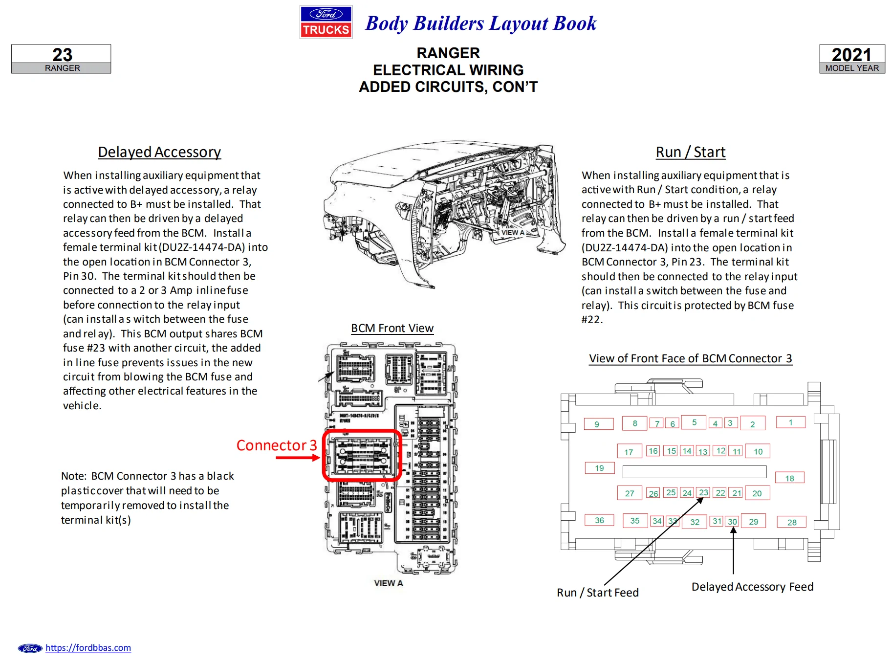
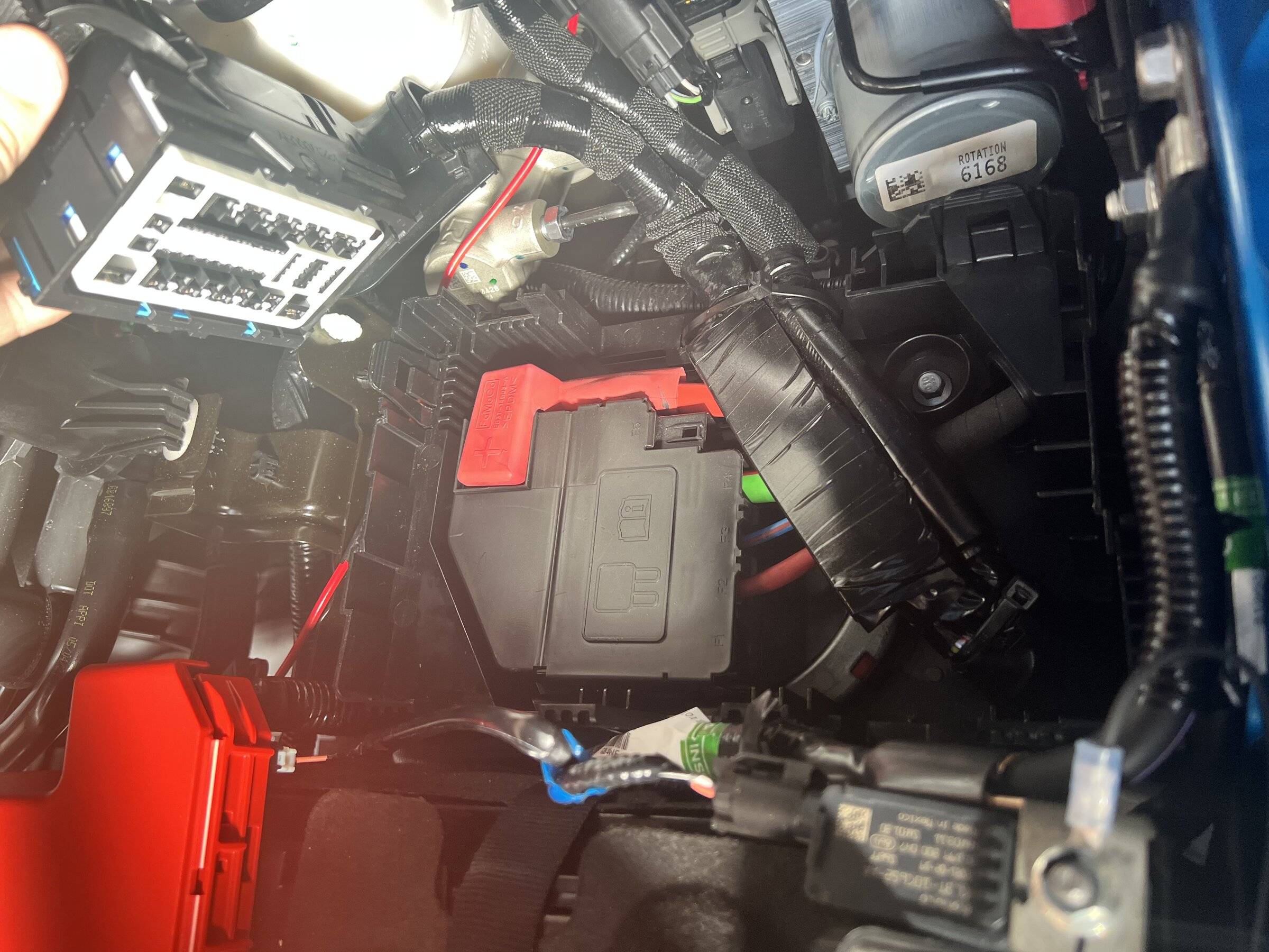
The connector I was going to tap for Fuse 19 was Connector 1035A - the left connector as you look at the fuse box from the front of the hood.

The pin I needed to tap was Pin 19.. however you'll see above I also circled Pin 30 here's why:

Unfortunately for me - Pin 19 AND Pin 30 are both a 20-gage brown wire with a white stripe.. dang. This is solvable though, but we'll need to do some trial and error.
First, I disconnected the negative lead on the battery (Important!), then Fully removed the interior fuse box. This isn't trivial but it's common - you'll need to do this if you ever have to change some of the bottom fuses. There's a good thread here on how to do this, with a damn good YouTube video of the process.
With the fuse box removed, you can see the 1035A and 1035B connector/harness cables run under the fuse box.

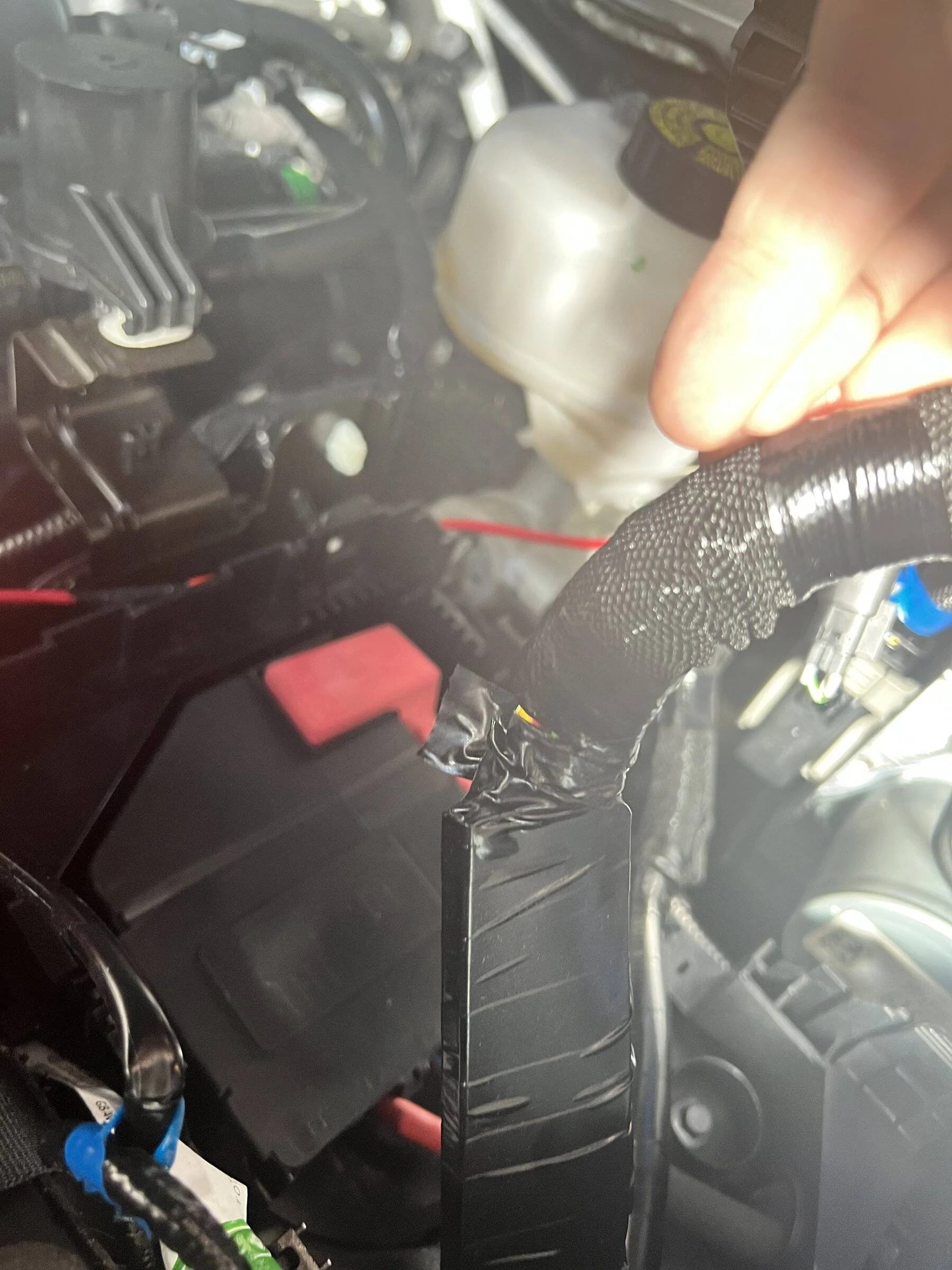
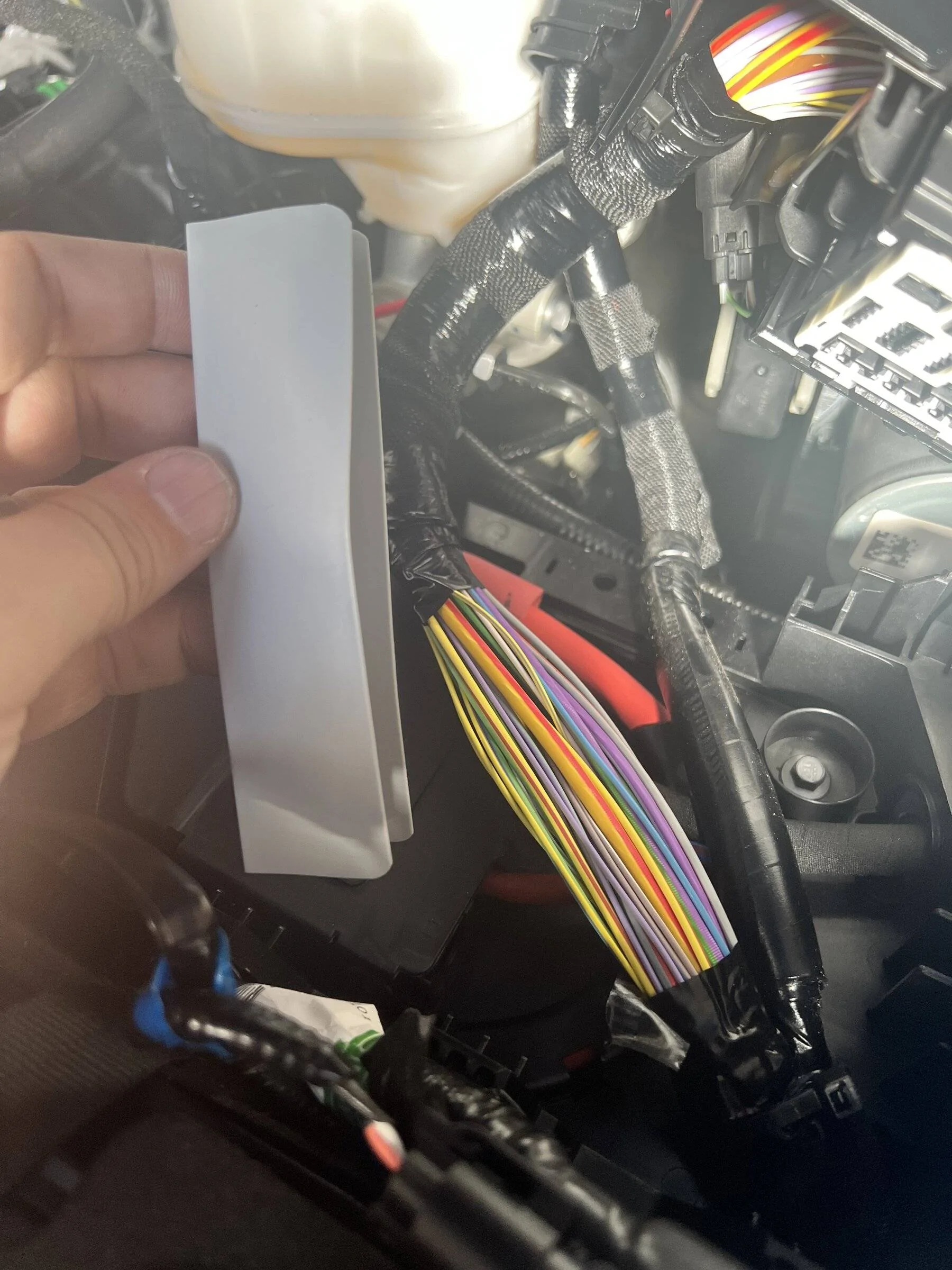
I cut the zip tie securing both connectors, and I removed the tape from the 1035A connector - it has a plastic shield taped around it.

Once the tape is gone and the shield is removed - yup, there are two 20-gage brown-with-white stripe wires! Note - these almost looked grey, not brown..
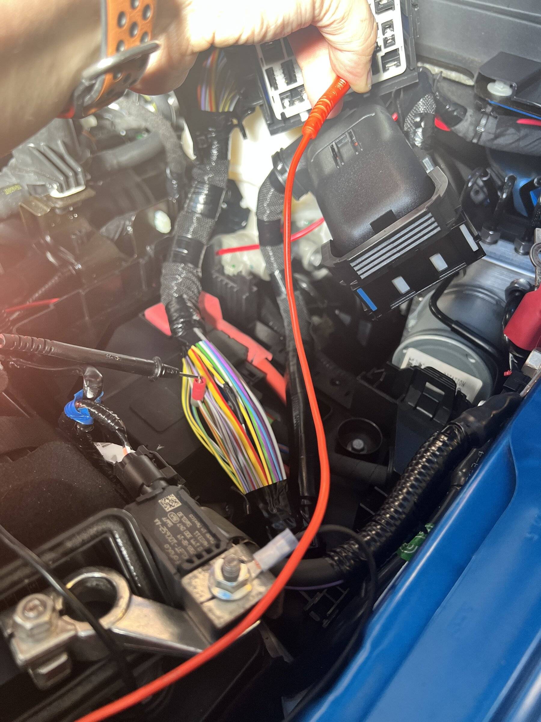
So what to do? The way I figured out the correct wire was to tap one, then use a multimeter continuity test and see if the tapped wire was Pin 19 or Pin 30.
The taps I used were Posi-Tap wire taps, as they are less "destructive" to the cables (in my opinion.) Not water tight, however.
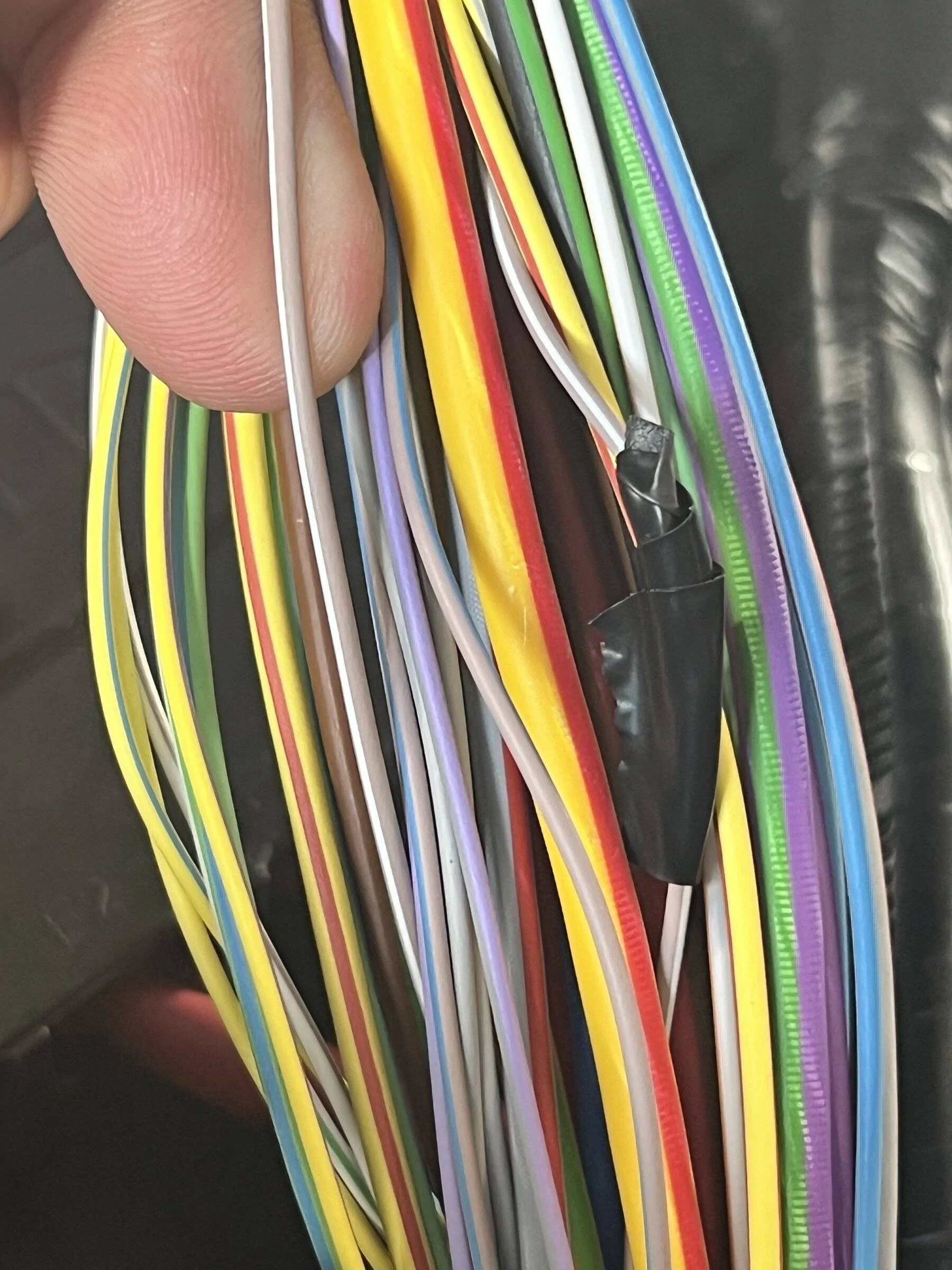
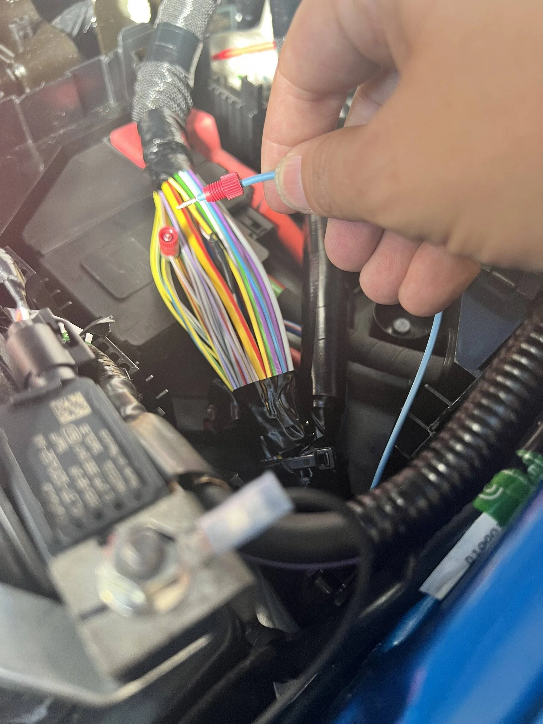
Well, the first one I picked and tapped was of course Pin 30. So I untapped it and taped over it to be safe. Here's a pic of the wrong wire (electric taped) and the correct wire (under finger.)
Tapping the other wire and success, the meter beeped on Pin 19.
Next, I routed the Switch-Pros blue wire under the plastic BJB mount - where the harness wires were run. Easy to get it it there by going along side the battery.
I used the tap to secure the blue wire to the tapped circuit.
After that, it was a matter of taping things back up
Reassembling, and testing - everything was good to go!
After about 24h of testing - everything is great so far.. we'll see if it stays that way.
Hope this helps someone else out, and if anyone thinks there could be issues how I did it - please let me know your thoughts!
WARNING: I'm often an idiot, and you might break stuff if you follow what I did. This is here for info/help with no warranty or guarantees.
I bought the kit from SDHQ to make the install easier - and it's a great kit.
However, the hard/fun part has been getting an Ignition source for the blue wire. The blue wire appears to just be a 12v sensor, and there's no real load on the circuit.
A lot of people have had varying suggestions - most along the lines of:
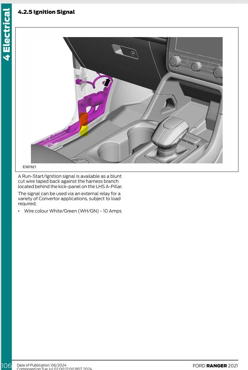
- Use a piggyback fuse and run a wire through the seal on the Battery Junction Box (Engine fuse box.)
- Run a wire through the firwall and use a piggyback fuse in the Body Control Module (Driver footwell fuse box.)
I started a thread here to find out wire colors/circuits - found the info myself and updated my own thread.. but the data here is what I used to make this work.
Armed with that info, I did some tests on my fuse box to find out which fuse would be a good candidate to tap. I finally decided to tap F19 - the Power Steering Control Module fuse. This fuse is ignition switched and came on as I expected and desired the ignition lead to work.
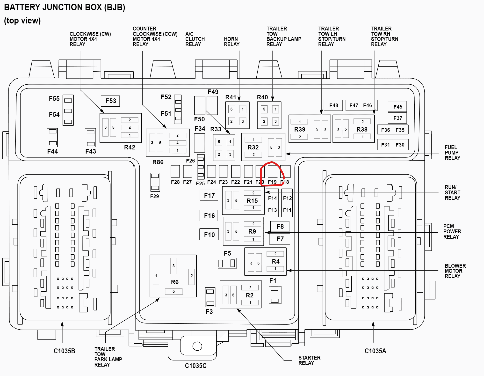

Now, If I'd done a piggyback connector - I could have just added a micro3 connector and been done. But I decided to go the complicated route. I pulled the connectors and tapped the wires under the fuse panel.
The connector I was going to tap for Fuse 19 was Connector 1035A - the left connector as you look at the fuse box from the front of the hood.
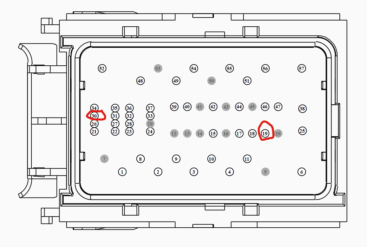
The pin I needed to tap was Pin 19.. however you'll see above I also circled Pin 30 here's why:

Unfortunately for me - Pin 19 AND Pin 30 are both a 20-gage brown wire with a white stripe.. dang. This is solvable though, but we'll need to do some trial and error.
First, I disconnected the negative lead on the battery (Important!), then Fully removed the interior fuse box. This isn't trivial but it's common - you'll need to do this if you ever have to change some of the bottom fuses. There's a good thread here on how to do this, with a damn good YouTube video of the process.
With the fuse box removed, you can see the 1035A and 1035B connector/harness cables run under the fuse box.
I cut the zip tie securing both connectors, and I removed the tape from the 1035A connector - it has a plastic shield taped around it.
Once the tape is gone and the shield is removed - yup, there are two 20-gage brown-with-white stripe wires! Note - these almost looked grey, not brown..
So what to do? The way I figured out the correct wire was to tap one, then use a multimeter continuity test and see if the tapped wire was Pin 19 or Pin 30.
The taps I used were Posi-Tap wire taps, as they are less "destructive" to the cables (in my opinion.) Not water tight, however.
Well, the first one I picked and tapped was of course Pin 30. So I untapped it and taped over it to be safe. Here's a pic of the wrong wire (electric taped) and the correct wire (under finger.)
Tapping the other wire and success, the meter beeped on Pin 19.
Next, I routed the Switch-Pros blue wire under the plastic BJB mount - where the harness wires were run. Easy to get it it there by going along side the battery.
I used the tap to secure the blue wire to the tapped circuit.
After that, it was a matter of taping things back up
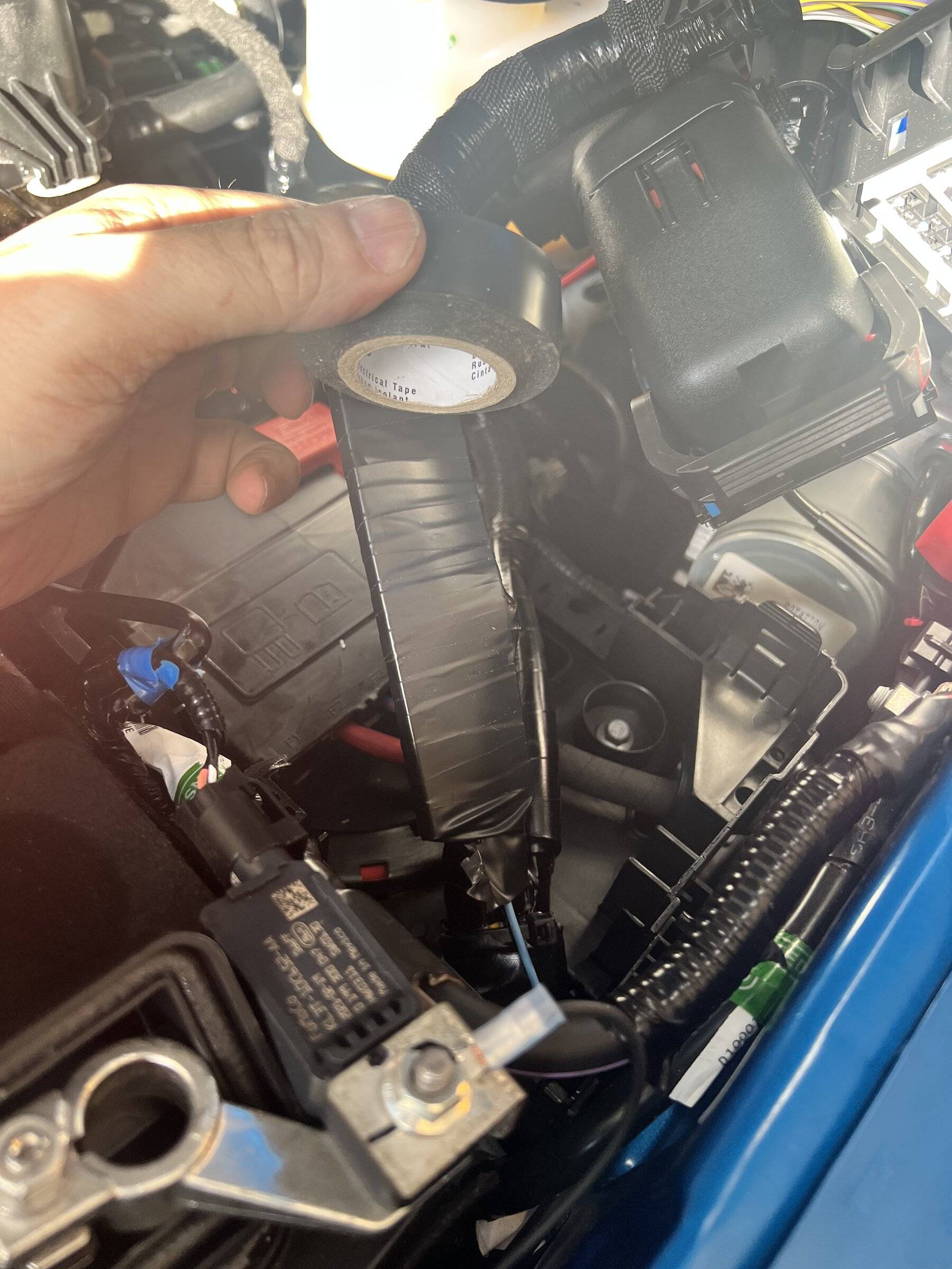
Reassembling, and testing - everything was good to go!
After about 24h of testing - everything is great so far.. we'll see if it stays that way.
Hope this helps someone else out, and if anyone thinks there could be issues how I did it - please let me know your thoughts!
Sponsored