Sponsored
OP
OP
boston
Active Member
- Thread starter
- #32
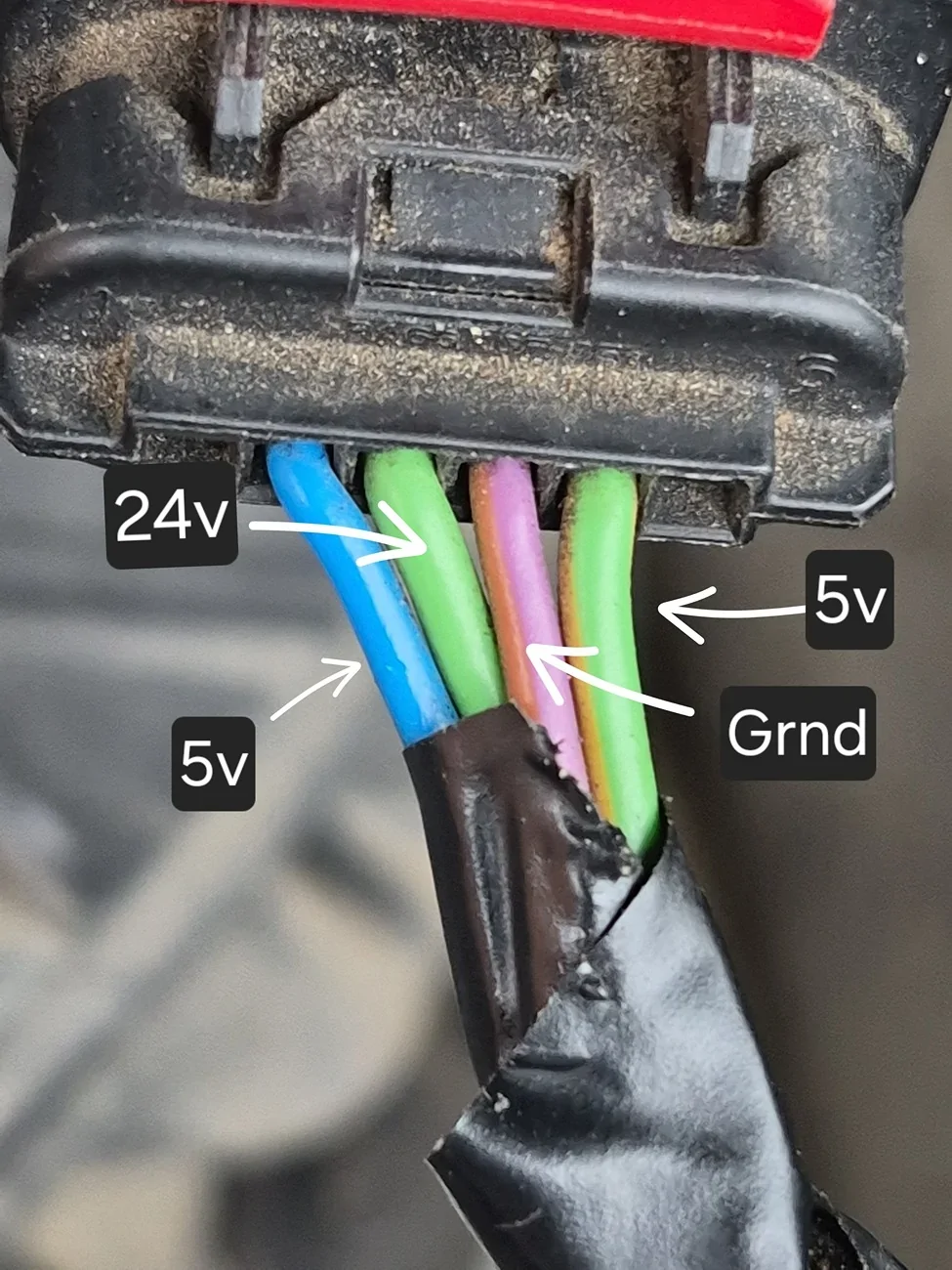
I've also checked voltages at plug. Green Yellow is signal back I think. Is this a modulated voltage? Are these correct? I've been trying to find data online but no luck. Its pointing more to an air leak.
I did look a PIDs for fuel rail pressures and throttle position all looks good. @airline tech

I did look a PIDs for fuel rail pressures and throttle position all looks good. @airline tech

airline tech
Well-Known Member
- Joined
- Aug 24, 2022
- Threads
- 28
- Messages
- 4,447
- Reaction score
- 8,498
- Location
- Midwest - KS
- Vehicle(s)
- 2022 Ranger Lariat-Super Crew, Cactus Gray
- Occupation
- Aircraft Tech
Just to confirm - You have replaced with (OEM) and still have issues
You are wire testing (Via) back probing - 24 Volts is not right and your KEEO and Idle readings are not right - I cannot locate a wire (pinout) diagram for the 3.2
Something is not right - either the sensor is shorted or the wiring is and I wish I could see the wiring diagram for proper wire testing
OP
OP
boston
Active Member
- Thread starter
- #34
Im trying to find it too. I will see whayvI can findJust to confirm - You have replaced with (OEM) and still have issues
You are wire testing (Via) back probing - 24 Volts is not right and your KEEO and Idle readings are not right - I cannot locate a wire (pinout) diagram for the 3.2
Something is not right - either the sensor is shorted or the wiring is and I wish I could see the wiring diagram for proper wire testing
airline tech
Well-Known Member
- Joined
- Aug 24, 2022
- Threads
- 28
- Messages
- 4,447
- Reaction score
- 8,498
- Location
- Midwest - KS
- Vehicle(s)
- 2022 Ranger Lariat-Super Crew, Cactus Gray
- Occupation
- Aircraft Tech
Is this the new Ford sensor or the Hella?Im trying to find it too. I will see whayvI can find
OP
OP
boston
Active Member
- Thread starter
- #36
Its was a bosch sensor not from ford. I've ordered a new map and maf from ford. It would be so good to find out if voltages are correct. Its booked in for the garage the 22nd. But will fit the Ford parts from ford this week.Is this the new Ford sensor or the Hella?
airline tech
Well-Known Member
- Joined
- Aug 24, 2022
- Threads
- 28
- Messages
- 4,447
- Reaction score
- 8,498
- Location
- Midwest - KS
- Vehicle(s)
- 2022 Ranger Lariat-Super Crew, Cactus Gray
- Occupation
- Aircraft Tech
If you put the OEM back in - does it return to the original issue?
OP
OP
boston
Active Member
- Thread starter
- #40
Code: P006A - MAP - Mass or Volume Air Flow Correlation Bank 1
Status (-64):
- DTC Maturing - Intermittent at Time of Request
- Malfunction Indicator Lamp is Off for this DTC
- Test not complete
Module: Powertrain Control Module
Freeze Frame #1:
-EVENT_TIME: 271777470 s (Tue Apr 14 12:56:41 2026) - Event time
-TOTAL_DISTANCE: 141430 km - Total Distance
-RUNTM: 475 s - Time Since Engine Start
-O2SHTR_EVAL: No - Heated Exhaust Oxygen Sensor Heater System Evaluated
-SAIR_EVAL: No - Secondary Air System Evaluated
-CATSUP_DC: NO - Catalyst
-AIRSUP_DC: YES - secondary air system supported
-CCM_EVAL: No - Comprehensive Components Monitor Evaluated
-CCMSUP_DC: YES - CCMON$I
-EVAPSUP_DC: NO - Evap system
-HCATSUP_DC: YES - Heated Catalyst
-HTRSUP_DC: YES - oxygen sensor heater monitor supported
-MISFSUP_DC: NO - misfire monitor supported
-CAT_EVAL: Yes - Catalyst Monitor Evaluated
-HCAT_EVAL: Yes - Heated Catalyst Monitor Evaluated
-EGR_EVAL: Yes - Exhaust Gas Recirculation System Evaluated
-EGRSUP_DC: YES - EGR system monitoring
-EVAP_EVAL: Yes - Evaporative System Monitor Evaluated
-FUEL_EVAL: No - Fuel System Monitor Evaluated
-FUEL_SUP: YES - fuel system monitor supported
-MIL: Off - Malfunction Indicator Lamp
-MISF_EVAL: Yes - Misfire Monitor Evaluated
-O2S_EVAL: Yes - Oxygen Sensor Monitor Evaluated
-O2SSUP_DC: YES - oxygen sensor monitor supported
-LOAD: 13.33 % - Calculated Load Value
-ECT: 58 °C - Engine coolant temperature
-MAP: 247.0 kPa - Manifold absolute pressure sensor
-RPM: 783 1/min - Engine Revolutions Per Minute
-VSS: 0.0 km/h - Vehicle Speed
-IAT: 22 °C - Intake Air Temperature
-MAF: 21.74 g/s - Mass Air Flow
-EGR_PCT: 0.00 % - Commanded EGR
-EGR_ERR: 0.00 % - EGR Difference Between Commanded And Actual
-BARO: 101.0 kPa - Barometric pressure
-AAT: 17 °C - Ambient Air Temperature
-APP_REL: 0.00 % - Accelerator Pedal Position Relative
-FRP_ABS: 35050.0 kPa - Fuel Rail Pressure (Absolute)
-CACT_DS: 19 °C - Charge-air temperature downstream from charge-air
-ACT: 19 °C - Air Charge Temperature
-EGR_LRN: -0 - Exhaust Gas Recirculation Valve Learning Value - Closed [mm]
-EGR_ERROR: -0.00 % - EGR Error
-ISV_LRN_C: -0.00 ° - Intake Shatter Valve Learning Value - Closed
-TP_ERROR: -0.00 % - Throttle Position Error
-TURBO_SOV_MES: 0.00 % - Turbo Shut Off Valve Opening Position - Measured
Code: P0234 - Turbocharger/Supercharger 'A' Overboost Condition
Status (-E4):
- DTC Maturing - Intermittent at Time of Request
- Malfunction Indicator Lamp is On for this DTC
- Test not complete
Module: Powertrain Control Module
Freeze Frame #1:
-EVENT_TIME: 271777956 s (Tue Apr 14 13:04:47 2026) - Event time
-TOTAL_DISTANCE: 141430 km - Total Distance
-RUNTM: 962 s - Time Since Engine Start
-O2SHTR_EVAL: No - Heated Exhaust Oxygen Sensor Heater System Evaluated
-SAIR_EVAL: No - Secondary Air System Evaluated
-CATSUP_DC: NO - Catalyst
-AIRSUP_DC: YES - secondary air system supported
-CCM_EVAL: No - Comprehensive Components Monitor Evaluated
-CCMSUP_DC: YES - CCMON$I
-EVAPSUP_DC: NO - Evap system
-HCATSUP_DC: YES - Heated Catalyst
-HTRSUP_DC: YES - oxygen sensor heater monitor supported
-MISFSUP_DC: NO - misfire monitor supported
-CAT_EVAL: Yes - Catalyst Monitor Evaluated
-HCAT_EVAL: Yes - Heated Catalyst Monitor Evaluated
-EGR_EVAL: Yes - Exhaust Gas Recirculation System Evaluated
-EGRSUP_DC: YES - EGR system monitoring
-EVAP_EVAL: Yes - Evaporative System Monitor Evaluated
-FUEL_EVAL: No - Fuel System Monitor Evaluated
-FUEL_SUP: YES - fuel system monitor supported
-MIL: Off - Malfunction Indicator Lamp
-MISF_EVAL: Yes - Misfire Monitor Evaluated
-O2S_EVAL: Yes - Oxygen Sensor Monitor Evaluated
-O2SSUP_DC: YES - oxygen sensor monitor supported
-LOAD: 28.24 % - Calculated Load Value
-ECT: 66 °C - Engine coolant temperature
-RPM: 1488 1/min - Engine Revolutions Per Minute
-VSS: 31.0 km/h - Vehicle Speed
-IAT: 19 °C - Intake Air Temperature
-MAF: 45.58 g/s - Mass Air Flow
-EGR_PCT: 0.00 % - Commanded EGR
-EGR_ERR: 0.00 % - EGR Difference Between Commanded And Actual
-BARO: 100.0 kPa - Barometric pressure
-AAT: 15 °C - Ambient Air Temperature
-APP_REL: 12.55 % - Accelerator Pedal Position Relative
-FRP_ABS: 73430.0 kPa - Fuel Rail Pressure (Absolute)
-CACT_DS: 19 °C - Charge-air temperature downstream from charge-air
-ACT: 19 °C - Air Charge Temperature
-EGR_LRN: -0 - Exhaust Gas Recirculation Valve Learning Value - Closed [mm]
-EGR_ERROR: -0.00 % - EGR Error
-ISV_LRN_C: -0.00 ° - Intake Shatter Valve Learning Value - Closed
-TP_ERROR: -0.00 % - Throttle Position Error
-TURBO_SOV_MES: 0.00 % - Turbo Shut Off Valve Opening Position - Measured
Code: P0069 - Manifold Absolute Pressure - Barometric Pressure Correlation
Additional Fault Symptom") 22):
22):
- Signal Amplitude Greater Than Maximum
Status (-E4):
- DTC Maturing - Intermittent at Time of Request
- Malfunction Indicator Lamp is On for this DTC
- Test not complete
Module: Powertrain Control Module
Freeze Frame #1:
-EVENT_TIME: 271779736 s (Tue Apr 14 13:34:27 2026) - Event time
-TOTAL_DISTANCE: 141446 km - Total Distance
-RUNTM: 2731 s - Time Since Engine Start
-O2SHTR_EVAL: No - Heated Exhaust Oxygen Sensor Heater System Evaluated
-SAIR_EVAL: No - Secondary Air System Evaluated
-CATSUP_DC: NO - Catalyst
-AIRSUP_DC: YES - secondary air system supported
-CCM_EVAL: No - Comprehensive Components Monitor Evaluated
-CCMSUP_DC: YES - CCMON$I
-EVAPSUP_DC: NO - Evap system
-HCATSUP_DC: YES - Heated Catalyst
-HTRSUP_DC: YES - oxygen sensor heater monitor supported
-MISFSUP_DC: NO - misfire monitor supported
-CAT_EVAL: Yes - Catalyst Monitor Evaluated
-HCAT_EVAL: Yes - Heated Catalyst Monitor Evaluated
-EGR_EVAL: Yes - Exhaust Gas Recirculation System Evaluated
-EGRSUP_DC: YES - EGR system monitoring
-EVAP_EVAL: Yes - Evaporative System Monitor Evaluated
-FUEL_EVAL: No - Fuel System Monitor Evaluated
-FUEL_SUP: YES - fuel system monitor supported
-MIL: Off - Malfunction Indicator Lamp
-MISF_EVAL: Yes - Misfire Monitor Evaluated
-O2S_EVAL: Yes - Oxygen Sensor Monitor Evaluated
-O2SSUP_DC: YES - oxygen sensor monitor supported
-LOAD: 0.00 % - Calculated Load Value
-ECT: 80 °C - Engine coolant temperature
-MAP: 251.0 kPa - Manifold absolute pressure sensor
-RPM: 0 1/min - Engine Revolutions Per Minute
-VSS: 0.0 km/h - Vehicle Speed
-IAT: 20 °C - Intake Air Temperature
-MAF: 2.77 g/s - Mass Air Flow
-EGR_PCT: 0.00 % - Commanded EGR
-EGR_ERR: 0.00 % - EGR Difference Between Commanded And Actual
-BARO: 100.0 kPa - Barometric pressure
-AAT: 16 °C - Ambient Air Temperature
-APP_REL: 0.00 % - Accelerator Pedal Position Relative
-FRP_ABS: 9580.0 kPa - Fuel Rail Pressure (Absolute)
-CACT_DS: 21 °C - Charge-air temperature downstream from charge-air
-ACT: 21 °C - Air Charge Temperature
-EGR_LRN: -0 - Exhaust Gas Recirculation Valve Learning Value - Closed [mm]
-EGR_ERROR: -0.00 % - EGR Error
-ISV_LRN_C: 0.89 ° - Intake Shatter Valve Learning Value - Closed
-TP_ERROR: 0.89 % - Throttle Position Error
-TP: 1.57 % - Throttle Position
-TURBO_SOV_MES: 31.37 % - Turbo Shut Off Valve Opening Position - Measured
Status (-64):
- DTC Maturing - Intermittent at Time of Request
- Malfunction Indicator Lamp is Off for this DTC
- Test not complete
Module: Powertrain Control Module
Freeze Frame #1:
-EVENT_TIME: 271777470 s (Tue Apr 14 12:56:41 2026) - Event time
-TOTAL_DISTANCE: 141430 km - Total Distance
-RUNTM: 475 s - Time Since Engine Start
-O2SHTR_EVAL: No - Heated Exhaust Oxygen Sensor Heater System Evaluated
-SAIR_EVAL: No - Secondary Air System Evaluated
-CATSUP_DC: NO - Catalyst
-AIRSUP_DC: YES - secondary air system supported
-CCM_EVAL: No - Comprehensive Components Monitor Evaluated
-CCMSUP_DC: YES - CCMON$I
-EVAPSUP_DC: NO - Evap system
-HCATSUP_DC: YES - Heated Catalyst
-HTRSUP_DC: YES - oxygen sensor heater monitor supported
-MISFSUP_DC: NO - misfire monitor supported
-CAT_EVAL: Yes - Catalyst Monitor Evaluated
-HCAT_EVAL: Yes - Heated Catalyst Monitor Evaluated
-EGR_EVAL: Yes - Exhaust Gas Recirculation System Evaluated
-EGRSUP_DC: YES - EGR system monitoring
-EVAP_EVAL: Yes - Evaporative System Monitor Evaluated
-FUEL_EVAL: No - Fuel System Monitor Evaluated
-FUEL_SUP: YES - fuel system monitor supported
-MIL: Off - Malfunction Indicator Lamp
-MISF_EVAL: Yes - Misfire Monitor Evaluated
-O2S_EVAL: Yes - Oxygen Sensor Monitor Evaluated
-O2SSUP_DC: YES - oxygen sensor monitor supported
-LOAD: 13.33 % - Calculated Load Value
-ECT: 58 °C - Engine coolant temperature
-MAP: 247.0 kPa - Manifold absolute pressure sensor
-RPM: 783 1/min - Engine Revolutions Per Minute
-VSS: 0.0 km/h - Vehicle Speed
-IAT: 22 °C - Intake Air Temperature
-MAF: 21.74 g/s - Mass Air Flow
-EGR_PCT: 0.00 % - Commanded EGR
-EGR_ERR: 0.00 % - EGR Difference Between Commanded And Actual
-BARO: 101.0 kPa - Barometric pressure
-AAT: 17 °C - Ambient Air Temperature
-APP_REL: 0.00 % - Accelerator Pedal Position Relative
-FRP_ABS: 35050.0 kPa - Fuel Rail Pressure (Absolute)
-CACT_DS: 19 °C - Charge-air temperature downstream from charge-air
-ACT: 19 °C - Air Charge Temperature
-EGR_LRN: -0 - Exhaust Gas Recirculation Valve Learning Value - Closed [mm]
-EGR_ERROR: -0.00 % - EGR Error
-ISV_LRN_C: -0.00 ° - Intake Shatter Valve Learning Value - Closed
-TP_ERROR: -0.00 % - Throttle Position Error
-TURBO_SOV_MES: 0.00 % - Turbo Shut Off Valve Opening Position - Measured
Code: P0234 - Turbocharger/Supercharger 'A' Overboost Condition
Status (-E4):
- DTC Maturing - Intermittent at Time of Request
- Malfunction Indicator Lamp is On for this DTC
- Test not complete
Module: Powertrain Control Module
Freeze Frame #1:
-EVENT_TIME: 271777956 s (Tue Apr 14 13:04:47 2026) - Event time
-TOTAL_DISTANCE: 141430 km - Total Distance
-RUNTM: 962 s - Time Since Engine Start
-O2SHTR_EVAL: No - Heated Exhaust Oxygen Sensor Heater System Evaluated
-SAIR_EVAL: No - Secondary Air System Evaluated
-CATSUP_DC: NO - Catalyst
-AIRSUP_DC: YES - secondary air system supported
-CCM_EVAL: No - Comprehensive Components Monitor Evaluated
-CCMSUP_DC: YES - CCMON$I
-EVAPSUP_DC: NO - Evap system
-HCATSUP_DC: YES - Heated Catalyst
-HTRSUP_DC: YES - oxygen sensor heater monitor supported
-MISFSUP_DC: NO - misfire monitor supported
-CAT_EVAL: Yes - Catalyst Monitor Evaluated
-HCAT_EVAL: Yes - Heated Catalyst Monitor Evaluated
-EGR_EVAL: Yes - Exhaust Gas Recirculation System Evaluated
-EGRSUP_DC: YES - EGR system monitoring
-EVAP_EVAL: Yes - Evaporative System Monitor Evaluated
-FUEL_EVAL: No - Fuel System Monitor Evaluated
-FUEL_SUP: YES - fuel system monitor supported
-MIL: Off - Malfunction Indicator Lamp
-MISF_EVAL: Yes - Misfire Monitor Evaluated
-O2S_EVAL: Yes - Oxygen Sensor Monitor Evaluated
-O2SSUP_DC: YES - oxygen sensor monitor supported
-LOAD: 28.24 % - Calculated Load Value
-ECT: 66 °C - Engine coolant temperature
-RPM: 1488 1/min - Engine Revolutions Per Minute
-VSS: 31.0 km/h - Vehicle Speed
-IAT: 19 °C - Intake Air Temperature
-MAF: 45.58 g/s - Mass Air Flow
-EGR_PCT: 0.00 % - Commanded EGR
-EGR_ERR: 0.00 % - EGR Difference Between Commanded And Actual
-BARO: 100.0 kPa - Barometric pressure
-AAT: 15 °C - Ambient Air Temperature
-APP_REL: 12.55 % - Accelerator Pedal Position Relative
-FRP_ABS: 73430.0 kPa - Fuel Rail Pressure (Absolute)
-CACT_DS: 19 °C - Charge-air temperature downstream from charge-air
-ACT: 19 °C - Air Charge Temperature
-EGR_LRN: -0 - Exhaust Gas Recirculation Valve Learning Value - Closed [mm]
-EGR_ERROR: -0.00 % - EGR Error
-ISV_LRN_C: -0.00 ° - Intake Shatter Valve Learning Value - Closed
-TP_ERROR: -0.00 % - Throttle Position Error
-TURBO_SOV_MES: 0.00 % - Turbo Shut Off Valve Opening Position - Measured
Code: P0069 - Manifold Absolute Pressure - Barometric Pressure Correlation
Additional Fault Symptom
22):- Signal Amplitude Greater Than Maximum
Status (-E4):
- DTC Maturing - Intermittent at Time of Request
- Malfunction Indicator Lamp is On for this DTC
- Test not complete
Module: Powertrain Control Module
Freeze Frame #1:
-EVENT_TIME: 271779736 s (Tue Apr 14 13:34:27 2026) - Event time
-TOTAL_DISTANCE: 141446 km - Total Distance
-RUNTM: 2731 s - Time Since Engine Start
-O2SHTR_EVAL: No - Heated Exhaust Oxygen Sensor Heater System Evaluated
-SAIR_EVAL: No - Secondary Air System Evaluated
-CATSUP_DC: NO - Catalyst
-AIRSUP_DC: YES - secondary air system supported
-CCM_EVAL: No - Comprehensive Components Monitor Evaluated
-CCMSUP_DC: YES - CCMON$I
-EVAPSUP_DC: NO - Evap system
-HCATSUP_DC: YES - Heated Catalyst
-HTRSUP_DC: YES - oxygen sensor heater monitor supported
-MISFSUP_DC: NO - misfire monitor supported
-CAT_EVAL: Yes - Catalyst Monitor Evaluated
-HCAT_EVAL: Yes - Heated Catalyst Monitor Evaluated
-EGR_EVAL: Yes - Exhaust Gas Recirculation System Evaluated
-EGRSUP_DC: YES - EGR system monitoring
-EVAP_EVAL: Yes - Evaporative System Monitor Evaluated
-FUEL_EVAL: No - Fuel System Monitor Evaluated
-FUEL_SUP: YES - fuel system monitor supported
-MIL: Off - Malfunction Indicator Lamp
-MISF_EVAL: Yes - Misfire Monitor Evaluated
-O2S_EVAL: Yes - Oxygen Sensor Monitor Evaluated
-O2SSUP_DC: YES - oxygen sensor monitor supported
-LOAD: 0.00 % - Calculated Load Value
-ECT: 80 °C - Engine coolant temperature
-MAP: 251.0 kPa - Manifold absolute pressure sensor
-RPM: 0 1/min - Engine Revolutions Per Minute
-VSS: 0.0 km/h - Vehicle Speed
-IAT: 20 °C - Intake Air Temperature
-MAF: 2.77 g/s - Mass Air Flow
-EGR_PCT: 0.00 % - Commanded EGR
-EGR_ERR: 0.00 % - EGR Difference Between Commanded And Actual
-BARO: 100.0 kPa - Barometric pressure
-AAT: 16 °C - Ambient Air Temperature
-APP_REL: 0.00 % - Accelerator Pedal Position Relative
-FRP_ABS: 9580.0 kPa - Fuel Rail Pressure (Absolute)
-CACT_DS: 21 °C - Charge-air temperature downstream from charge-air
-ACT: 21 °C - Air Charge Temperature
-EGR_LRN: -0 - Exhaust Gas Recirculation Valve Learning Value - Closed [mm]
-EGR_ERROR: -0.00 % - EGR Error
-ISV_LRN_C: 0.89 ° - Intake Shatter Valve Learning Value - Closed
-TP_ERROR: 0.89 % - Throttle Position Error
-TP: 1.57 % - Throttle Position
-TURBO_SOV_MES: 31.37 % - Turbo Shut Off Valve Opening Position - Measured
airline tech
Well-Known Member
- Joined
- Aug 24, 2022
- Threads
- 28
- Messages
- 4,447
- Reaction score
- 8,498
- Location
- Midwest - KS
- Vehicle(s)
- 2022 Ranger Lariat-Super Crew, Cactus Gray
- Occupation
- Aircraft Tech
I am going to use a (Possible) Pinout - Not Confirmed - (Left To Right)
Pin 1 (Blue) = IAT Signal
Pin 2 (Green) = 12 Volt Power Supply
Pin 3 (Violet / Red) = Signal Return / Ground
Pin 4 (Green / Orange) = MAF Signal
KOEO - Sensor Disconnected (Meter)
Black Lead to (Battery Negative) and Red Lead to each pin
Pin 2 - 5 Volts
Pin 3 - 12 Volts
Pin 4 - 0 volts
Pin 5 -0 Volts
Then (Red Lead to Battery Positive) and Black Lead to
Pin 4 = 12 Volts
I may have the IAT & MAF Signal (Swapped)
Just a quick wire check - as the 24 Volt Reading has me questioning that voltage reading accuracy
I am also thinking that
The 4 wires consist of
Power - 12 Volts
Ground - For Heater (Chassis)
Map - 5-Volt VREF
Signal Rtn (MAP) & the PCM uses this as its signal (pick-up)
Last edited:
OP
OP
boston
Active Member
- Thread starter
- #42
Crap I made a mistake its 12v not 24v. I work as an electrical engineer and control voltage is 24v. I was in autopilot when I made the image. Sorry. Pin 5 has me guessing. Its got 5v on it. Surely the return should not have a voltage if the sensor is not plugged in?
I am going to use a (Possible) Pinout - Not Confirmed - (Left To Right)
Pin 1 (Blue) = IAT Signal
Pin 2 (Green) = 12 Volt Power Supply
Pin 3 (Violet / Red) = Signal Return / Ground
Pin 4 (Green / Orange) = MAF Signal
KOEO - Sensor Disconnected (Meter)
Black Lead to (Battery Negative) and Red Lead to each pin
Pin 2 - 5 Volts
Pin 3 - 12 Volts
Pin 4 - 0 volts
Pin 5 -0 Volts
Then (Red Lead to Battery Positive) and Black Lead to
Pin 4 = 12 Volts
I may have the IAT & MAF Signal (Swapped)
Just a quick wire check - as the 24 Volt Reading has me questioning that voltage reading accuracy
I am also thinking that
The 4 wires consist of
Power - 12 Volts
Ground - For Heater (Chassis)
Map - 5-Volt VREF
Signal Rtn (MAP) & the PCM uses this as its signal (pick-up)
Or does this get modulated and sent back on pin 4?
airline tech
Well-Known Member
- Joined
- Aug 24, 2022
- Threads
- 28
- Messages
- 4,447
- Reaction score
- 8,498
- Location
- Midwest - KS
- Vehicle(s)
- 2022 Ranger Lariat-Super Crew, Cactus Gray
- Occupation
- Aircraft Tech
correct the IAT should read 5 volts (with it unplugged) and the MAF should read (0 volts)
airline tech
Well-Known Member
- Joined
- Aug 24, 2022
- Threads
- 28
- Messages
- 4,447
- Reaction score
- 8,498
- Location
- Midwest - KS
- Vehicle(s)
- 2022 Ranger Lariat-Super Crew, Cactus Gray
- Occupation
- Aircraft Tech
Another possible is sometimes the Signal Wire is also 5 volts (unplugged) the PCM provides 5 volts on the signal wire and the sensor provides the ground path
The 5 Volt VREF is simply power only to the sensor.
The signal return is a 5 Volt supply and the resistance to ground = MAF signal
The 12 volt supply is for the heater and the ground is for the heater circuit.
I think the above would make the most logical sense with your readings via back probing - and you have no MAF signal and you are speed limited - it is in Limp Mode
So for me the MAF that is installed is bad and this is why it would be a good idea to reinstall the original and see what it does.
Sponsored