BronzedAussie
Member
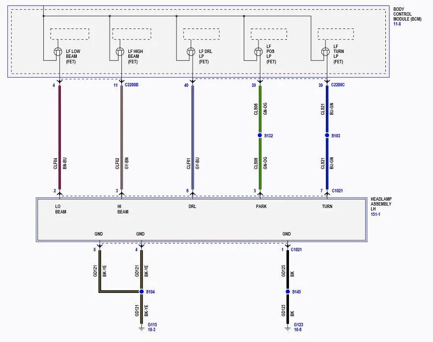
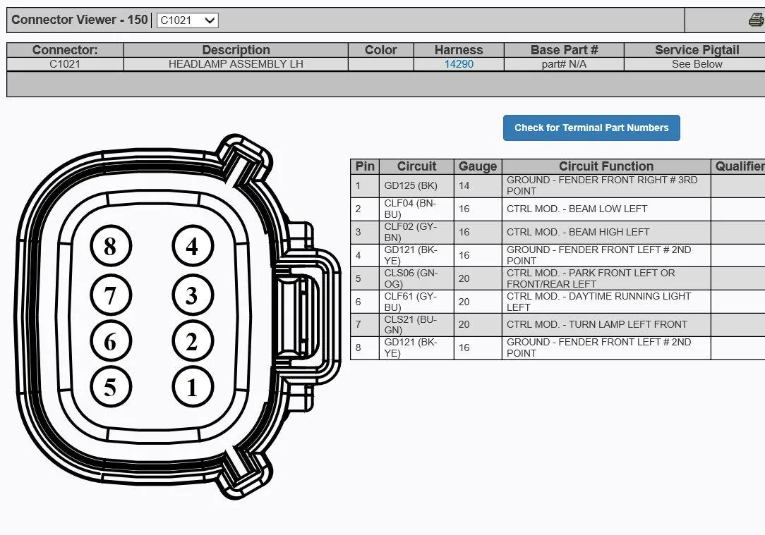
Yep, if you read my next reply to the one you quoted, you'll see I found out the only difference to the diagram given at the start of this thread for AU is to ignore the indicator pin (when you look at our lights you can see the indicator wiring doesn't go into the main headlight loom). All the other pins ring true. So you want pin 6 from that diagram.Hi BronzedAussie, do you have drawings of lights connector fo Australian Ranger? I have 2021 Wildtrak model. I'm trying to find out which pin is for DRL. Thank you kindly.
Sponsored