airline tech
Well-Known Member
- Joined
- Aug 24, 2022
- Threads
- 28
- Messages
- 4,461
- Reaction score
- 8,529
- Location
- Midwest - KS
- Vehicle(s)
- 2022 Ranger Lariat-Super Crew, Cactus Gray
- Occupation
- Aircraft Tech
Ok,
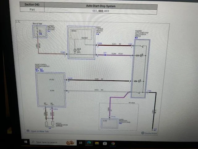
Sometimes it helps to get another view of things and using the F-150 and the bypass write-up above, I can see the internal operation a bit clearer.
F-150 - Diagram
So, what the guy in the write-up has done is removed the momentary switch and installed a toggle for the switch
He has cut the White (pin #2) and Purple (his description and not actually clear pic) but (pin #3) is the wire he cut - is actually Black / Villot) by the diagram, which is the ground for the switch.
What this diagram tells me, that the Ranger diagrams does not is the detail of the switch itself
(Normally Open), with the Ranger diagrams it was unknown (less detail)

So, for the Ranger including the OP's 2017 it may be possible to use the same bypass with a toggle as the operational function should be the same.
The way I see the operation is you press the switch (momentarily)
This applies a temporary ground to a microcontroller (switch) internal of the FCIM which grounds and turns on the light in the switch (disabled)
This disabled ground also sends this information via the data buss that the system is disabled and communicates to the rest of the modules in the system, mainly the IPC to give you the message and indicator light on the dash.
So, in essence the disabled light is the actual control circuit for the ASS system as long as that light is (on) the system is disabled. (If I am correct)
The unknown is, will the FCIM software trigger a (Stuck Switch) failure code?
I do not like or recommend the process of just diking wires, but its your truck and it may possibly work without any faults.
Now to clarify, We in the US do not have easy access (I do not) to ROW Ranger Manuals, therefor I cannot get a Connector View or Pinout of the wiring for your truck. The connectors are not the same for US Rangers and wire pinouts are different.
With that said, it does appear that the wire colors possibly match.
Since we are only looking for 2-wires, this should be fairly easy.
The White / Brown - Should be the ASS Switch (Output)
The Black / Villot- Should be the Mult switch (Ground)
To test get a meter (set to Ohm's scale) and test the switch itself (disconnected)
match the White / Brown - Connector Wire to the Switch Pin for location ident as well as the Black / Villot.
Connect the meter leads to those pins and press and release the ASS switch, you should be seeing continuity when pressed and open when released. This will ident the proper wires to cut for a toggle install.
If you do this, please be sure to give yourself a length of wire long enough from the connector to resplice it back together (if needed) or you will need to replace the connector
A preferred option would be to get a wiretap and tap into those wire with a toggle, no cutting required. This way you are still forcing the switch to ground (palmately)
Sometimes it helps to get another view of things and using the F-150 and the bypass write-up above, I can see the internal operation a bit clearer.
F-150 - Diagram
So, what the guy in the write-up has done is removed the momentary switch and installed a toggle for the switch
He has cut the White (pin #2) and Purple (his description and not actually clear pic) but (pin #3) is the wire he cut - is actually Black / Villot) by the diagram, which is the ground for the switch.
What this diagram tells me, that the Ranger diagrams does not is the detail of the switch itself
(Normally Open), with the Ranger diagrams it was unknown (less detail)
So, for the Ranger including the OP's 2017 it may be possible to use the same bypass with a toggle as the operational function should be the same.
The way I see the operation is you press the switch (momentarily)
This applies a temporary ground to a microcontroller (switch) internal of the FCIM which grounds and turns on the light in the switch (disabled)
This disabled ground also sends this information via the data buss that the system is disabled and communicates to the rest of the modules in the system, mainly the IPC to give you the message and indicator light on the dash.
So, in essence the disabled light is the actual control circuit for the ASS system as long as that light is (on) the system is disabled. (If I am correct)
The unknown is, will the FCIM software trigger a (Stuck Switch) failure code?
I do not like or recommend the process of just diking wires, but its your truck and it may possibly work without any faults.
Now to clarify, We in the US do not have easy access (I do not) to ROW Ranger Manuals, therefor I cannot get a Connector View or Pinout of the wiring for your truck. The connectors are not the same for US Rangers and wire pinouts are different.
With that said, it does appear that the wire colors possibly match.
Since we are only looking for 2-wires, this should be fairly easy.
The White / Brown - Should be the ASS Switch (Output)
The Black / Villot- Should be the Mult switch (Ground)
To test get a meter (set to Ohm's scale) and test the switch itself (disconnected)
match the White / Brown - Connector Wire to the Switch Pin for location ident as well as the Black / Villot.
Connect the meter leads to those pins and press and release the ASS switch, you should be seeing continuity when pressed and open when released. This will ident the proper wires to cut for a toggle install.
If you do this, please be sure to give yourself a length of wire long enough from the connector to resplice it back together (if needed) or you will need to replace the connector
A preferred option would be to get a wiretap and tap into those wire with a toggle, no cutting required. This way you are still forcing the switch to ground (palmately)
Sponsored