Frenchy
Well-Known Member
- First Name
- Chris
- Joined
- Mar 15, 2020
- Threads
- 164
- Messages
- 7,543
- Reaction score
- 10,752
- Location
- Elizabeth, Colorado
- Vehicle(s)
- 2012 Nissan Frontier, 1994 F150 XL, 2022 Ford Transit
- Occupation
- Field Service Technician
- Thread starter
- #1
Hoping this will become a Sticky as I feel this is important stuff for those to know.
This particular Thread is to help those who don't understand the Variable Voltage Systems that are on many Modern Vehicles today.
After a bit of time in both Automotive and the Forklift Industry, I have been able to get a bunch of information together to help me get an understanding. Once I had the understanding, it had me at ease vs when I was introduced to it and asking why it won't stay at 14.7 Volts.
Now to go over the basics.
For starters there are two types of Charging Systems. The old Conventional Charging System and the new Variable Voltage System. I don't know what manufacturer first introduced the Variable Voltage System, but I want to say it first started around the early 2000's.
The old Conventional Charging System was set to try and keep Battery Voltage around 14.4-14.7 Volts while the Vehicle is Running. If anything it would apply more Amps as needed when loads are applied. Not a bad thing necessarily, but not the best way to do things.
On modern vehicles you have the Variable Voltage Systems. The excuse Vehicle Manufacturers give us for the system is to help improve Fuel Economy. Honestly I feel that is a bit of BS as the fuel savings are miniscule. But that doesn't mean there isn't an advantage to it.
The real advantage of a Variable Voltage System is to Charge the Battery as needed. If the Battery is already at a full charge, then why push it further? Overcharging a Battery can Damage it. In reality you want to look at the Variable Voltage System as a Fancy Battery Charger that you would have at home plugged into the wall. The Battery Charger you have at home already has Programmed Charging Profiles for a few different types of Batteries. This is to help the Battery Charge Efficiently and Safely without Damaging the Battery. The Variable Voltage System acts in a similar way.
Now of course different vehicle manufacturers will vary how they operate, but most will be very similar to what I am about to explain. Once you get this part, it will be fairly easy to understand what's going on.
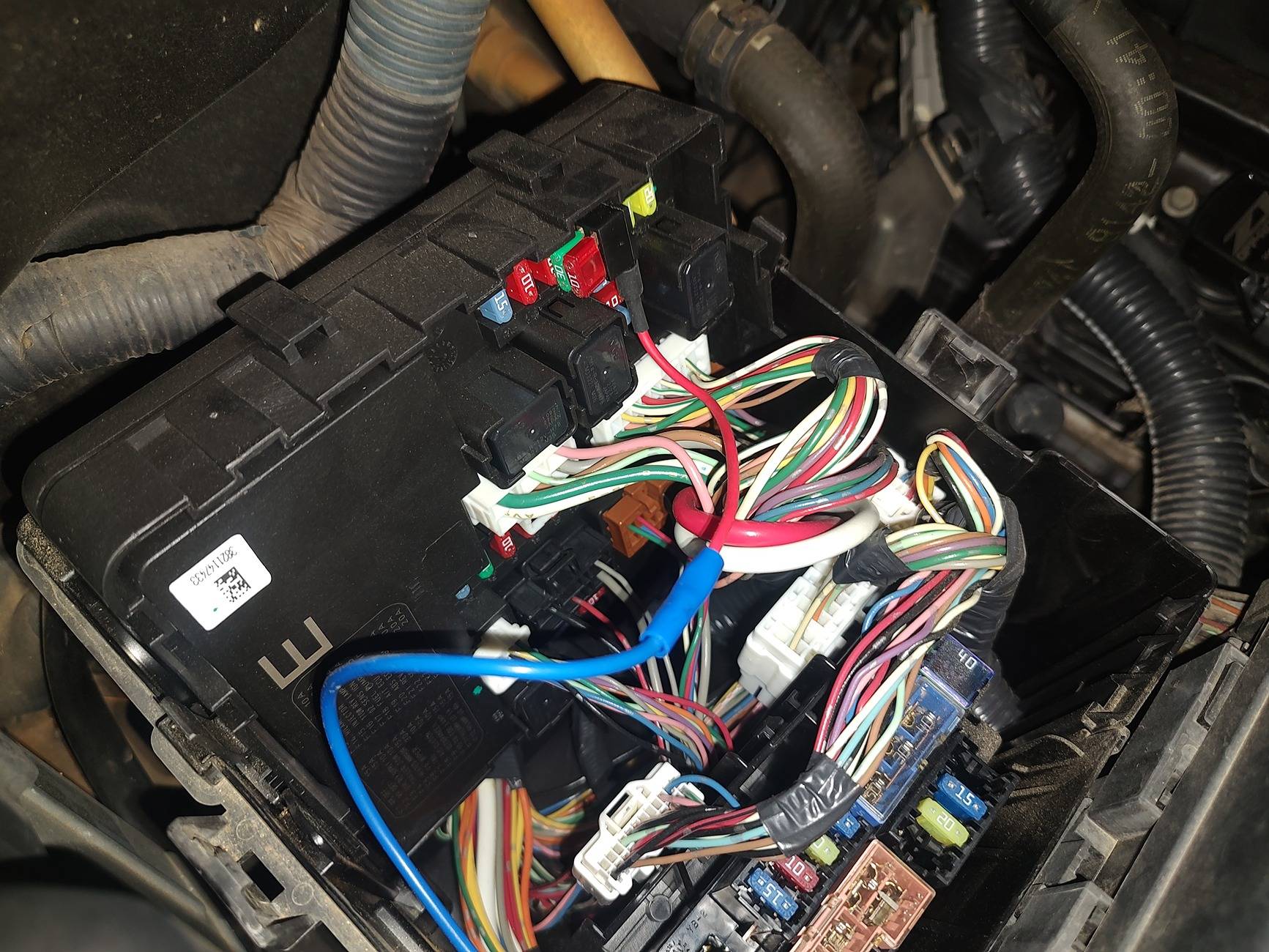
For a vehicle with Variable Voltage, there is one key component. That component is the Amp Meter on the Ground Cable. Depending on the vehicle will depend on the shape. This can have either 2 or 3 wires going to it. This particular sensor simply measures the Total Amps being pulled from any Electrical Load from the Vehicle and any Additional Aftermarket Equipment that may have been added(like Auxiliary Lights or a DC-DC Charger for an Auxiliary Battery). It also measures the Charge going in from a small Battery Charger like a Battery Tender or the NOCO Battery Maintainer that Ford Offers.
Now I would have to see the wiring diagram for the for the Ranger and I'm sure a certain someone(@airline tech ) can assist with this, but I believe the Amp Meter is wired directly to the ECM/PCM and the Data is sent to the BCM VIA CAN Communication. After that the BCM calculates the the Battery State of Charge along with the Amp Load applied so it can tell the Alternator to be at any set Voltage ranging from 12.7-14.7 Volts with an Amperage upto 180 Amps(I thing that is the Factory Amp Rating for the Alternator at least). This basically means that even if the truck is running at 13 Volts because that battery is charged, it can still apply 100 Amps at 13 Volts if the 100 Amp Load is applied from Factory Vehicle Equipment and any Additional Aftermarket Equipment that you have added.
Now that we have that bit over with, let's talk about wiring in Aftermarket Equipment correctly so the Variable Voltage System operates normally.
As mentioned above, the Variable Voltage System has an Amp Meter on the Ground Cable. It is Important that does not get Bypassed. If you do, the Amp Meter will not see all the Loads being pulled and the Alternator will not be able to Apply the Necessary Amps at any given Voltage to make sure the Battery is Charged Correctly. It can also cause multiple Vehicle Systems like the Radio to not operate Normally and be very Glitchy.
Now for any Aftermarket Equipment you add, you have the Okay from every Vehicle Manufacturer to pull the 12 Volt Positive strait from the Battery. As for the Ground, it is Extremely Important that you go to either the Body or the Chassis for the Ground. This will help ensure that the Amp Meter on the Ground Cable will be able to read the Amp Load so the Alternator can Apply the correct Amperage at any Given Voltage that is Commanded.
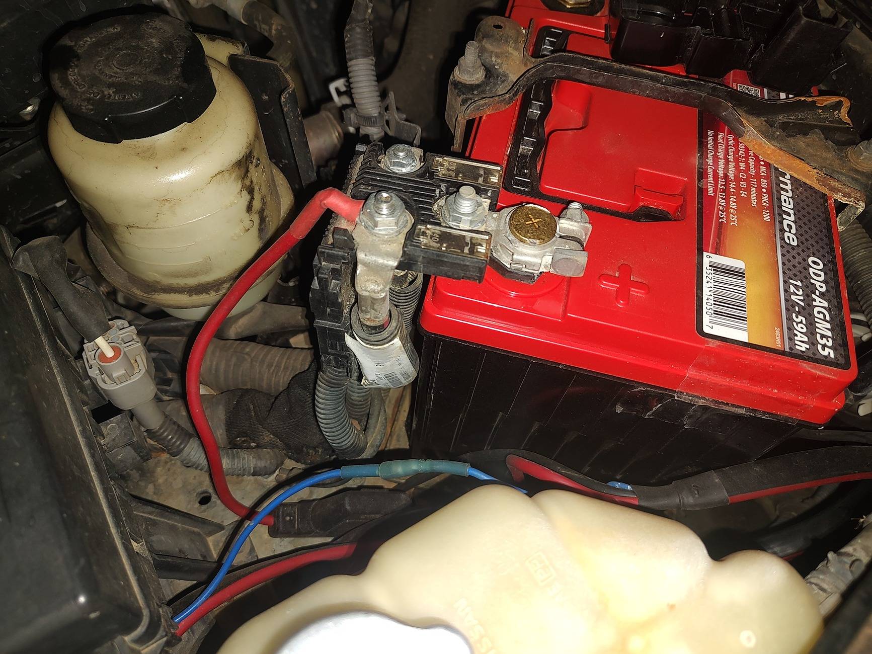
Though it is on a different type of vehicle, here is a great example of what to do. This particular example is on my 2012 Frontier that is also equipped with a Variable Voltage System.
This is for a DC-DC Charger and the same Principle will apply for the Ranger and other Vehicles with the Variable Voltage System.
For starters I did connect to the Positive Battery Terminal for the Power Itself. With a good clean connection like such, it shouldn't be an issue. Just keep in mind that if you are going to have multiple Electrical Equipment added, you might want a fair size Cable going to a Bridge.

For the Ground I simply found a good Body Ground near the Battery. This helps ensure the the Amp Meter will see the Load from the DC-DC Charger.(Phone wants to be a pain, so I will add a picture later)
Now because I have Variable Voltage, I had to make sure the DC-DC Charger has a way to work at a Lower Voltage. The one I have has a Signal wire. This wire should go to a Switched Power from the Ignition. This wire tells the DC-DC Charger to turn on at a Lower Voltage when it gets 12 Volt Power.
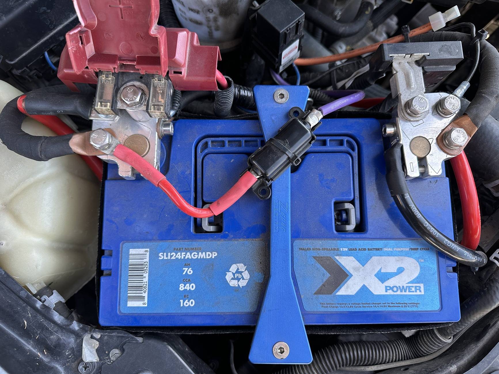
Now here is an example of what not to do!!!! This is also on a Nissan Frontier from someone who thought they knew what they were doing(spoiler alert, they didn't know what they were doing). On the Positive Side of the Battery it is ok. Probably a bit better than what I have honestly, but I'm not going to worry about it. As for the Ground Side..... That is a Disaster........ Adding all the Ground Cables like this will make any and all Electrical Loads bypass the Amp Meter and not allow the Alternator to apply the Correct Amount of Amps at any Voltage.
Hopefully this has been very helpful to those that are curious and didn't know much about the Variable Voltage System.
This particular Thread is to help those who don't understand the Variable Voltage Systems that are on many Modern Vehicles today.
After a bit of time in both Automotive and the Forklift Industry, I have been able to get a bunch of information together to help me get an understanding. Once I had the understanding, it had me at ease vs when I was introduced to it and asking why it won't stay at 14.7 Volts.
Now to go over the basics.
For starters there are two types of Charging Systems. The old Conventional Charging System and the new Variable Voltage System. I don't know what manufacturer first introduced the Variable Voltage System, but I want to say it first started around the early 2000's.
The old Conventional Charging System was set to try and keep Battery Voltage around 14.4-14.7 Volts while the Vehicle is Running. If anything it would apply more Amps as needed when loads are applied. Not a bad thing necessarily, but not the best way to do things.
On modern vehicles you have the Variable Voltage Systems. The excuse Vehicle Manufacturers give us for the system is to help improve Fuel Economy. Honestly I feel that is a bit of BS as the fuel savings are miniscule. But that doesn't mean there isn't an advantage to it.
The real advantage of a Variable Voltage System is to Charge the Battery as needed. If the Battery is already at a full charge, then why push it further? Overcharging a Battery can Damage it. In reality you want to look at the Variable Voltage System as a Fancy Battery Charger that you would have at home plugged into the wall. The Battery Charger you have at home already has Programmed Charging Profiles for a few different types of Batteries. This is to help the Battery Charge Efficiently and Safely without Damaging the Battery. The Variable Voltage System acts in a similar way.
Now of course different vehicle manufacturers will vary how they operate, but most will be very similar to what I am about to explain. Once you get this part, it will be fairly easy to understand what's going on.
For a vehicle with Variable Voltage, there is one key component. That component is the Amp Meter on the Ground Cable. Depending on the vehicle will depend on the shape. This can have either 2 or 3 wires going to it. This particular sensor simply measures the Total Amps being pulled from any Electrical Load from the Vehicle and any Additional Aftermarket Equipment that may have been added(like Auxiliary Lights or a DC-DC Charger for an Auxiliary Battery). It also measures the Charge going in from a small Battery Charger like a Battery Tender or the NOCO Battery Maintainer that Ford Offers.
Now I would have to see the wiring diagram for the for the Ranger and I'm sure a certain someone(@airline tech ) can assist with this, but I believe the Amp Meter is wired directly to the ECM/PCM and the Data is sent to the BCM VIA CAN Communication. After that the BCM calculates the the Battery State of Charge along with the Amp Load applied so it can tell the Alternator to be at any set Voltage ranging from 12.7-14.7 Volts with an Amperage upto 180 Amps(I thing that is the Factory Amp Rating for the Alternator at least). This basically means that even if the truck is running at 13 Volts because that battery is charged, it can still apply 100 Amps at 13 Volts if the 100 Amp Load is applied from Factory Vehicle Equipment and any Additional Aftermarket Equipment that you have added.
Now that we have that bit over with, let's talk about wiring in Aftermarket Equipment correctly so the Variable Voltage System operates normally.
As mentioned above, the Variable Voltage System has an Amp Meter on the Ground Cable. It is Important that does not get Bypassed. If you do, the Amp Meter will not see all the Loads being pulled and the Alternator will not be able to Apply the Necessary Amps at any given Voltage to make sure the Battery is Charged Correctly. It can also cause multiple Vehicle Systems like the Radio to not operate Normally and be very Glitchy.
Now for any Aftermarket Equipment you add, you have the Okay from every Vehicle Manufacturer to pull the 12 Volt Positive strait from the Battery. As for the Ground, it is Extremely Important that you go to either the Body or the Chassis for the Ground. This will help ensure that the Amp Meter on the Ground Cable will be able to read the Amp Load so the Alternator can Apply the correct Amperage at any Given Voltage that is Commanded.
Though it is on a different type of vehicle, here is a great example of what to do. This particular example is on my 2012 Frontier that is also equipped with a Variable Voltage System.
This is for a DC-DC Charger and the same Principle will apply for the Ranger and other Vehicles with the Variable Voltage System.
For starters I did connect to the Positive Battery Terminal for the Power Itself. With a good clean connection like such, it shouldn't be an issue. Just keep in mind that if you are going to have multiple Electrical Equipment added, you might want a fair size Cable going to a Bridge.
For the Ground I simply found a good Body Ground near the Battery. This helps ensure the the Amp Meter will see the Load from the DC-DC Charger.(Phone wants to be a pain, so I will add a picture later)
Now because I have Variable Voltage, I had to make sure the DC-DC Charger has a way to work at a Lower Voltage. The one I have has a Signal wire. This wire should go to a Switched Power from the Ignition. This wire tells the DC-DC Charger to turn on at a Lower Voltage when it gets 12 Volt Power.
Now here is an example of what not to do!!!! This is also on a Nissan Frontier from someone who thought they knew what they were doing(spoiler alert, they didn't know what they were doing). On the Positive Side of the Battery it is ok. Probably a bit better than what I have honestly, but I'm not going to worry about it. As for the Ground Side..... That is a Disaster........ Adding all the Ground Cables like this will make any and all Electrical Loads bypass the Amp Meter and not allow the Alternator to apply the Correct Amount of Amps at any Voltage.
Hopefully this has been very helpful to those that are curious and didn't know much about the Variable Voltage System.
Sponsored