Sponsored

(TM) rotary switch-wiring diagram

Pasparakis

Active Member
First Name
Pasparakis
Joined
Sep 16, 2021
Threads
3
Messages
43
Reaction score
4
Location
Greece
Vehicle(s)
Ranger wildtrak 2.0 biturbo 213ps
Occupation
6 months
Hello!!
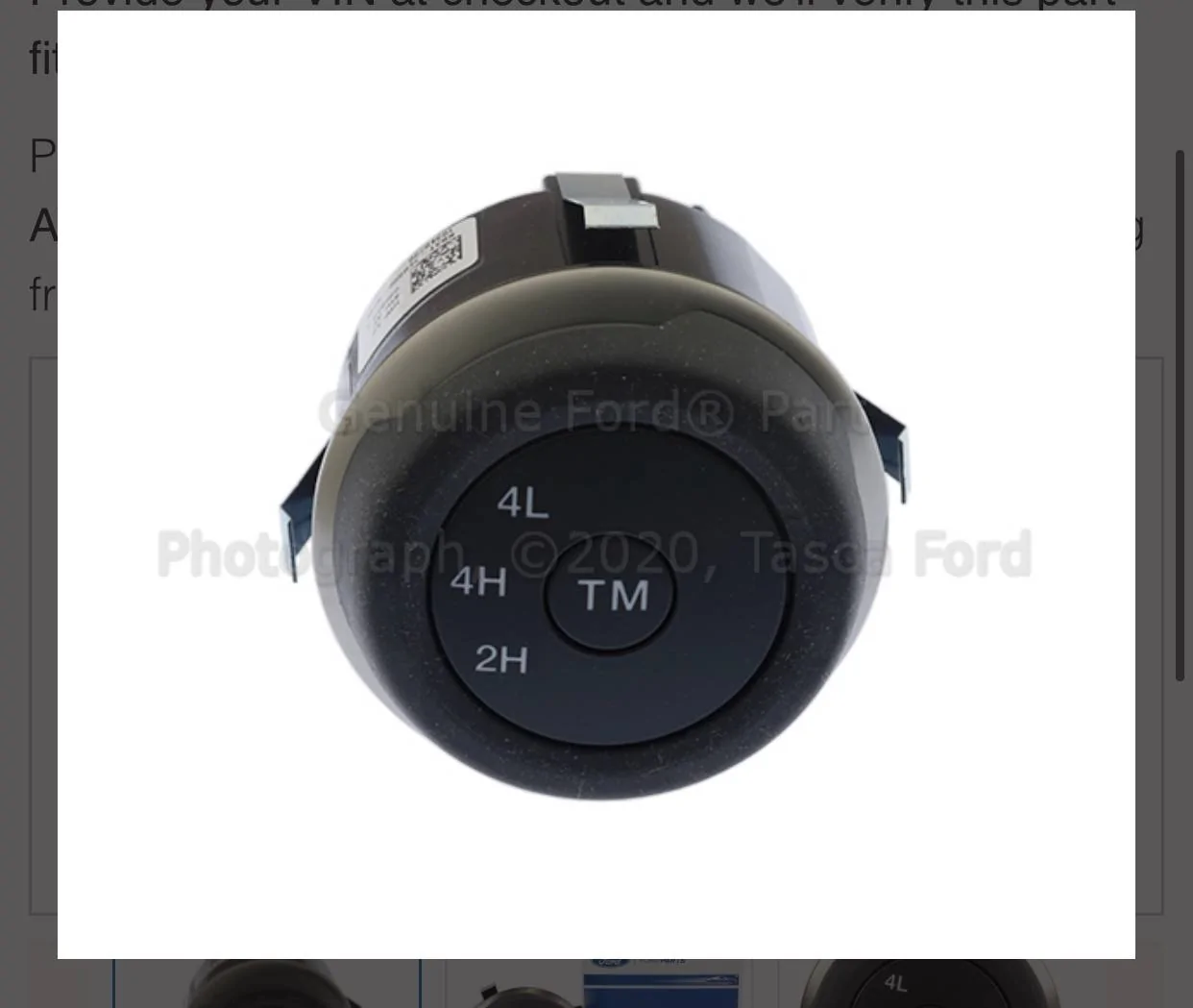
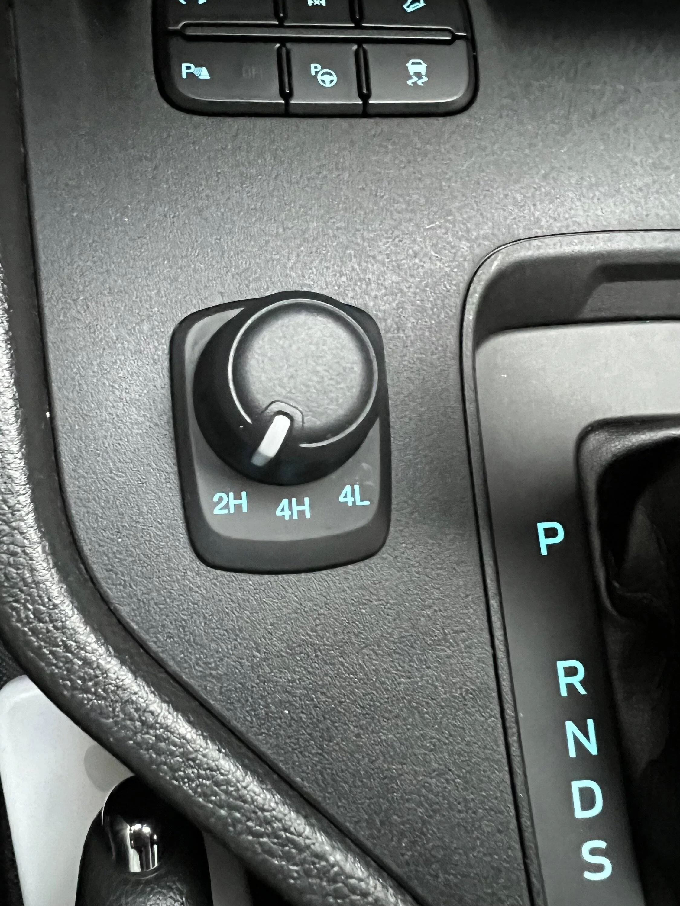
I need wiring diagram from rotary switch with (TM) button option..

IMG_1211.webp


IMG_1212.webp
Sponsored


ControlNode

Well-Known Member
First Name
John
Joined
Nov 29, 2021
Threads
16
Messages
1,709
Reaction score
3,640
Location
Eastern NC
Vehicle(s)
84 Civic "2000S"/16 Focus RS/21 Ranger XLT
Occupation
Computers
That should be C3393 and it should be wired like this:
Code:
PIN - Circuit (color) - Gauge - Function
1 - CBB23 (BN-YE) - 18 - FUSE 23 OR circuit breaker
2 - not used
3 - VDB25 (GN-OG) - 22 - Diagnostic # CAN BUS HS 2 (Upper) High
4 - absent
5 - not used
6 - VDB26 (GY-BU) - 22 - Diagnostic # CAN BUS HS 2 (Upper) Low
7 - GD345 (BK-BU) - 18 - Ground (Piller B Right)
8 - absent
The wiring is the same with or without the TM option.
 
OP
OP
Pasparakis

Pasparakis

Active Member
First Name
Pasparakis
Joined
Sep 16, 2021
Threads
3
Messages
43
Reaction score
4
Location
Greece
Vehicle(s)
Ranger wildtrak 2.0 biturbo 213ps
Occupation
6 months
Thank you for your reply!!
i want to replace my switch (European) with us models and once I'm done with that I'll activate “selectable drive mode” from forscan..I hope the experiment succeeds..

the European switch plug is different and I want to see if I can do it..

IMG_1227.webp
 

PltFX4

Well-Known Member
First Name
Richard
Joined
Jan 29, 2020
Threads
26
Messages
692
Reaction score
1,269
Location
Minneapolis, MN
Vehicle(s)
2019 Ranger Lariat FX4
Thank you for your reply!!
i want to replace my switch (European) with us models and once I'm done with that I'll activate “selectable drive mode” from forscan..I hope the experiment succeeds..

the European switch plug is different and I want to see if I can do it..
Just curious: Why?? seems yours is 4 pins and looks like the USA version only uses 4 pins of the 8 available, so do-able (one hopes).

How about a face on photo of the EU version... if there is a difference.


OP
OP
Pasparakis

Pasparakis

Active Member
First Name
Pasparakis
Joined
Sep 16, 2021
Threads
3
Messages
43
Reaction score
4
Location
Greece
Vehicle(s)
Ranger wildtrak 2.0 biturbo 213ps
Occupation
6 months
hope i can make this mod..
This is face:

IMG_6925.webp
 
OP
OP
Pasparakis

Pasparakis

Active Member
First Name
Pasparakis
Joined
Sep 16, 2021
Threads
3
Messages
43
Reaction score
4
Location
Greece
Vehicle(s)
Ranger wildtrak 2.0 biturbo 213ps
Occupation
6 months
if anyone has something like this from a manual..but with the right one..
 
Last edited:

ControlNode

Well-Known Member
First Name
John
Joined
Nov 29, 2021
Threads
16
Messages
1,709
Reaction score
3,640
Location
Eastern NC
Vehicle(s)
84 Civic "2000S"/16 Focus RS/21 Ranger XLT
Occupation
Computers
I looked in my US 2021 Ranger Wiring Diagrams manual for the information I shared.
 

ControlNode

Well-Known Member
First Name
John
Joined
Nov 29, 2021
Threads
16
Messages
1,709
Reaction score
3,640
Location
Eastern NC
Vehicle(s)
84 Civic "2000S"/16 Focus RS/21 Ranger XLT
Occupation
Computers
I found a 2017 Everest wiring diagram, (the part number that appears on the switches of that style I found on UK eBay crosses to it as well). But if I'm reading it right You can't use the US switch as ours is just CAN-Bus HS Hi&low, power and ground. The way I read the switch wiring in the Everest is Illumination (BN), ground (BK-BU or BK-VT), 4WD diff lock signal (GY), 4x4 low ratio signal (WH-GN).

If you're plug matches the colors above, you should be able to see ground on the 4wd diff lock output when in 4H. And, when in 4L you should see ground on 4x4 Low ratio output, maybe on 4wd diff lock output too.

But I'm not really familiar with ROW Fords so I may be wrong.

It does look like the ROW TM button is separate from the transfer case control switch (2H-4H-4L) and does use the CAN-BUS HS2 to communicate with the Transfer Case Control Module.


..... I guess if you are really adventurous you could look into adding RasberryPi or Arduino with a CAN-BUS shield that monitors for the US switches transfer case mode request, then using relays simulate the OE (to your market) switch. But you may need to add a way for the microPC to know the what mode the transfer case is in so that it can pass that over the CAN-BUS back to the US switch so it illuminates the current mode. Not sure all the messages that get passes around, but I'm guessing at least 3 from the switch and at least 7 back to it.


These are just guesses.
From switch:
  • TM Toggle
  • Rotor turned right (+)
  • Rotor turned left (-)
To Switch:
  • Switching to 2H
  • In 2H
  • Switching to 4H
  • In 4H
  • Switching to 4L
  • In 4L
  • Illumination on/off
  • Illumination dimming
  • Any TM feedback to the switch if there are any (I don't have the TM switch in mine, maybe they are only shown on the dash)
 
Last edited:
OP
OP
Pasparakis

Pasparakis

Active Member
First Name
Pasparakis
Joined
Sep 16, 2021
Threads
3
Messages
43
Reaction score
4
Location
Greece
Vehicle(s)
Ranger wildtrak 2.0 biturbo 213ps
Occupation
6 months
I found a 2017 Everest wiring diagram, (the part number that appears on the switches of that style I found on UK eBay crosses to it as well). But if I'm reading it right You can't use the US switch as ours is just CAN-Bus HS Hi&low, power and ground. The way I read the switch wiring in the Everest is Illumination (BN), ground (BK-BU or BK-VT), 4WD diff lock signal (GY), 4x4 low ratio signal (WH-GN).

If you're plug matches the colors above, you should be able to see ground on the 4wd diff lock output when in 4H. And, when in 4L you should see ground on 4x4 Low ratio output, maybe on 4wd diff lock output too.

But I'm not really familiar with ROW Fords so I may be wrong.

It does look like the ROW TM button is separate from the transfer case control switch (2H-4H-4L) and does use the CAN-BUS HS2 to communicate with the Transfer Case Control Module.


..... I guess if you are really adventurous you could look into adding RasberryPi or Arduino with a CAN-BUS shield that monitors for the US switches transaxles mode request, then using relays simulate the OE (to your market) switch. But you may need to add a way for the microPC to know the what mode the transfer case is in so that it can pass that over the CAN-BUS back to the US switch so it illuminates the current mode. Not sure all the messages that get passes around, but I'm guessing at least 3 from the switch and at least 7 back to it.


These are just guesses.
From switch:
  • TM Toggle
  • Rotor turned right (+)
  • Rotor turned left (-)
To Switch:
  • Switching to 2H
  • In 2H
  • Switching to 4H
  • In 4H
  • Switching to 4L
  • In 4L
  • Illumination on/off
  • Illumination dimming
  • Any TM feedback to the switch if there are any (I don't have the TM switch in mine, maybe they are only shown on the dash)

First of all, thank you for your answers...
You help me to complete the work..
I'll try as soon as I get my rotary switch..

It would help me even more if I had a photo from module diagram..(US) models..
like this :
 
Last edited:
OP
OP
Pasparakis

Pasparakis

Active Member
First Name
Pasparakis
Joined
Sep 16, 2021
Threads
3
Messages
43
Reaction score
4
Location
Greece
Vehicle(s)
Ranger wildtrak 2.0 biturbo 213ps
Occupation
6 months
Or better this wiring from (US MODELS)

this is from (European) models :

IMG_6934.webp
 

ControlNode

Well-Known Member
First Name
John
Joined
Nov 29, 2021
Threads
16
Messages
1,709
Reaction score
3,640
Location
Eastern NC
Vehicle(s)
84 Civic "2000S"/16 Focus RS/21 Ranger XLT
Occupation
Computers
Looking at the diagrams for your switch and the one at the US switch. No way to directly wire in in place of the other. The US only connects to a power source, a ground, and the HS2 CAN BUS HI&LOW. Therefore, they will not interchange, there's no way swap them with just repinning connectors. You would have to make some type of translation device that can talk to the US rotary switch at a CAN BUS level and then convert that to a resistor (if I'm reading your diagram right) based signal that's your the rest of your truck wants. Then you'd still have to add sensors to that translation unit or inputs from the truck system enough that that unit can then send the messages back to the US switch so it can indicate the correct mode.

I am not going to share images from the copyrighted manual. But I assure you there are places online you can find it with a search.
 
OP
OP
Pasparakis

Pasparakis

Active Member
First Name
Pasparakis
Joined
Sep 16, 2021
Threads
3
Messages
43
Reaction score
4
Location
Greece
Vehicle(s)
Ranger wildtrak 2.0 biturbo 213ps
Occupation
6 months
Looking at the diagrams for your switch and the one at the US switch. No way to directly wire in in place of the other. The US only connects to a power source, a ground, and the HS2 CAN BUS HI&LOW. Therefore, they will not interchange, there's no way swap them with just repinning connectors. You would have to make some type of translation device that can talk to the US rotary switch at a CAN BUS level and then convert that to a resistor (if I'm reading your diagram right) based signal that's your the rest of your truck wants. Then you'd still have to add sensors to that translation unit or inputs from the truck system enough that that unit can then send the messages back to the US switch so it can indicate the correct mode.

I am not going to share images from the copyrighted manual. But I assure you there are places online you can find it with a search.
now i understand you..my switch is not can bus..
the difficult thing is how to build what you tell me?
is there any way to build?
I think impossible?
 

ControlNode

Well-Known Member
First Name
John
Joined
Nov 29, 2021
Threads
16
Messages
1,709
Reaction score
3,640
Location
Eastern NC
Vehicle(s)
84 Civic "2000S"/16 Focus RS/21 Ranger XLT
Occupation
Computers
now i understand you..my switch is not can bus..
the difficult thing is how to build what you tell me?
is there any way to build?
I think impossible?
As I posted in one of my previous posts, you can get little computer, like a raspberry pi or Arduino, and use a can bus shield attachment for it. But you'll still need to design all the circuits to replicate your switch to the truck's original expectation and the controlling logic to receive and send the proper can bus signals from the rotary switch and potentially other systems of the truck especially if you're trying to use the integrated TM switch.
 

airline tech

Well-Known Member
Joined
Aug 24, 2022
Threads
28
Messages
4,447
Reaction score
8,497
Location
Midwest - KS
Vehicle(s)
2022 Ranger Lariat-Super Crew, Cactus Gray
Occupation
Aircraft Tech
I have looked at this as well, and I believe as far as the switch goes, it MAY work, as all the switch is doing is providing contact points in the switch to command the relays to power.
However, I believe the TM button will not be active., since the US version is Data Bus, the Non-Us wiring will not register it being pressed.
The other issue will be getting it into 4-LOW, it possibly may not switch into it.

It highly depends on how the internals of the US versions of the switch is made, I am thinking that it should be a normal switch (contact points), and all that differs is how the switch position is communicated. (CAN vs Direct Wire)
One other issue can the switch handle 12v's on the CAN Bus Terminals and will it provide enough voltage to the relays to make them power.
FYI: We cannot see the internal diagram of the switch (US Version), only pinouts.

If you have already ordered the switch, it may be at least worth a try.
How does your version of the Ranger switch into TM, is it a separate switch?

Edit:
I just remembered something, the US version switch, will rotate 360 degrees, so this may create an issue, the 3 positions are picked up from the data bus.

Edit #2:

Well crap, I looked at the Euro, diagram again and noted / saw the signal return, so this is most likely a 5-Volt Reference (?) circuit to the PCM, then the PCM sends the info along to the relays which are going to be 12-volt relays. I was looking at both Euro and US. :facepalm: 
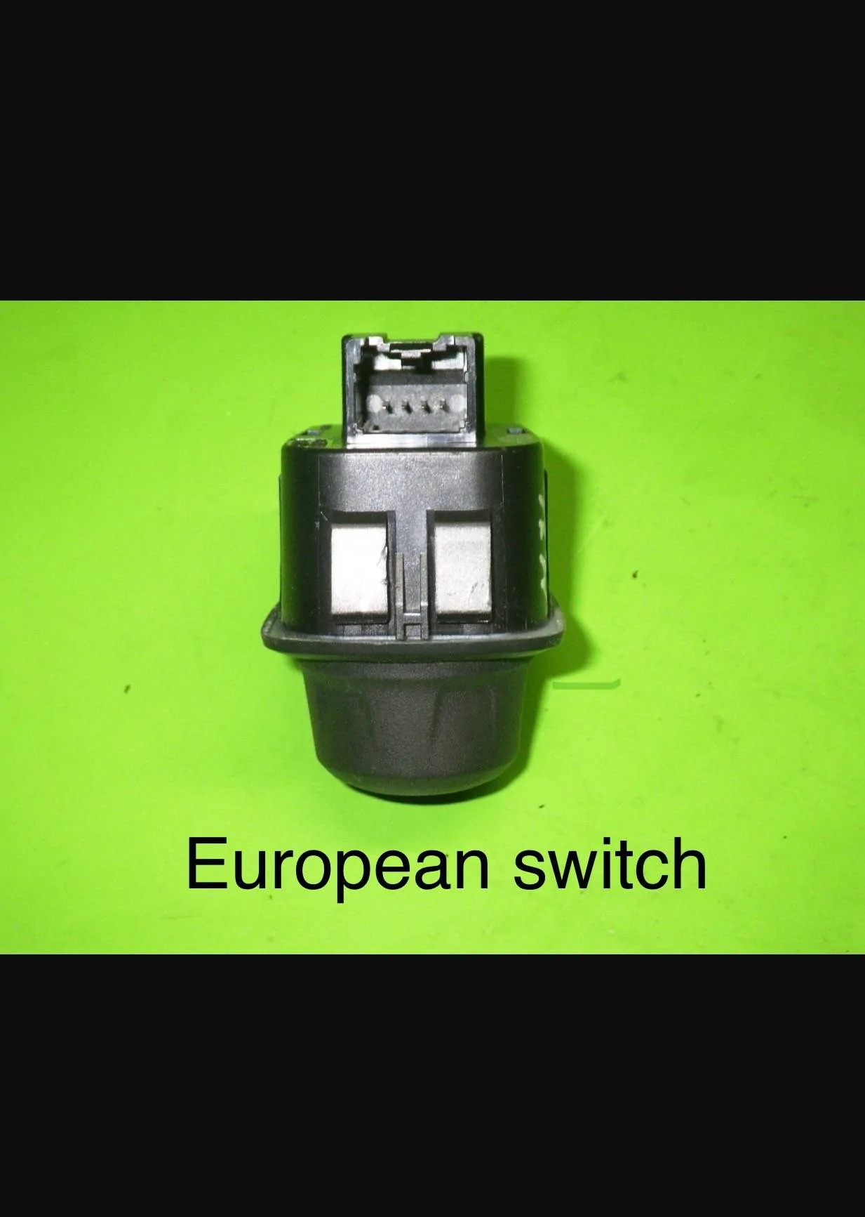
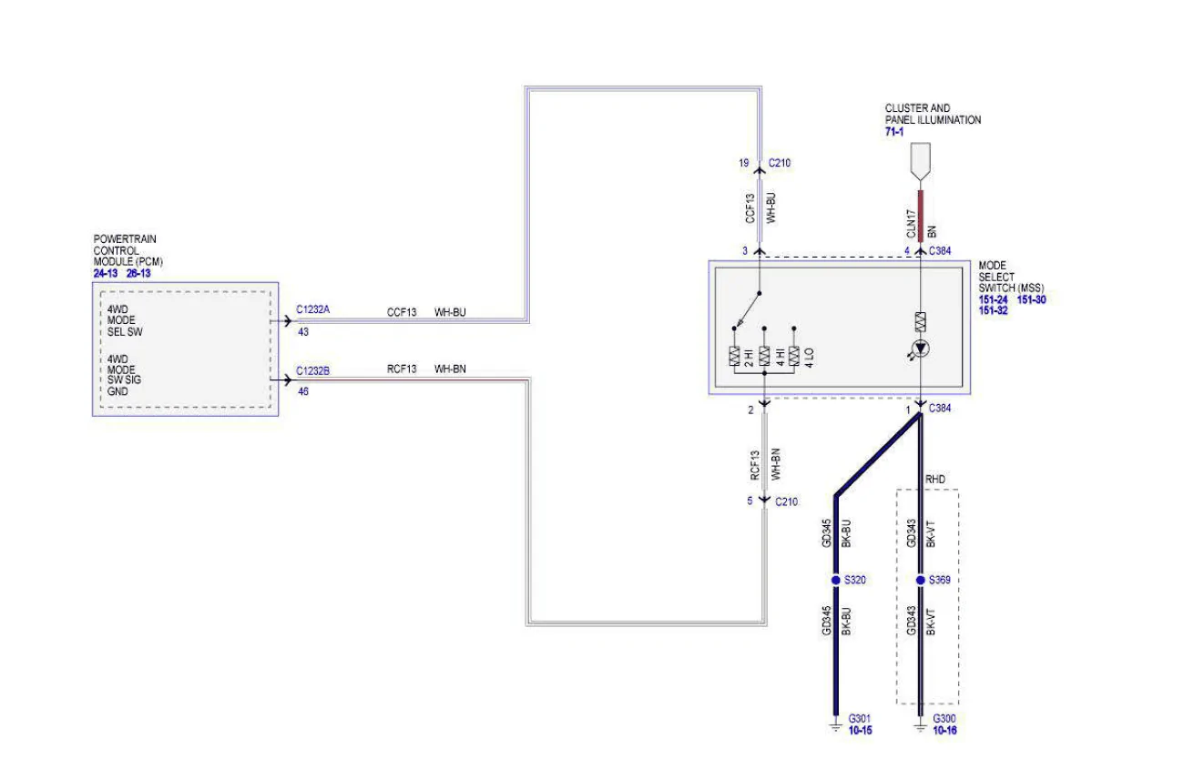
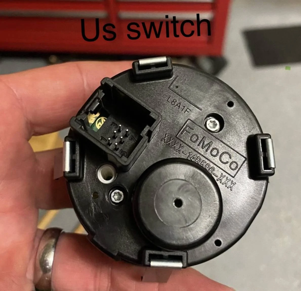
and had a rotary switch in my head. (Signal return = Switch Position via the voltage measured on the return circuit) the voltage will vary depending on switch position from the voltage drop across each resistor (switch position)

? = Reference circuits can vary in voltage, and I cannot see what Euro uses, the only way to tell for sure is to measure the input voltage without actually seeing the full wiring manual for this truck.
It could be 5, 9 or 12 volts. But I thinking it is a 5-Volt circuit.

Now, the US version switch should be similar, however with the switch being able to rotate 360 degrees I don't know if the PCM would actually pick up the switch position without an external control device like ControlNode has posted.
The US version should have a resistor set like the Euro version, but the resistor voltage drop will most likely be different and the PCM won't be able to read switch position.
Sponsored

 
Last edited:


Top