Muffin1
Well-Known Member
- Thread starter
- #1
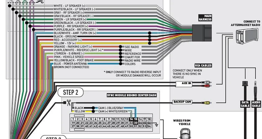
I'm almost finished up installing a Kenwood HU with the supplied harnesses' from idatalink, Maestro Rr interface,
HR/FO2 and Ken2, before i permanently reinstall i checked out what was working and what was not.
The BU camera is not coming on in Reverse, i have the yellow RCA plug into the HU and that is part of the Maestro harness, everything was plug/play no splicing.
Anyone who went from the 4.2 to the larger HU have any issues?
How did you wire up the BU camera?
Thanks,
Rob.
Sponsored
Last edited:

 .
.