AZRangerDood
Well-Known Member
- First Name
- Danny
- Joined
- Sep 21, 2020
- Threads
- 10
- Messages
- 63
- Reaction score
- 128
- Location
- Phoenix, Arizona
- Website
- www.instagram.com
- Vehicle(s)
- 2020 Ford Ranger XLT FX4
- Occupation
- Software Engineer
- Vehicle Showcase
- 1
- Thread starter
- #1
I built a custom relay fuse block capable of supporting 5 accessories a few weeks ago and have been pretty happy with the results so I figured I'd share the parts list and process for those who may also want to centralize their electronics and not spend a small fortune on controller/switch system. I think I spent somewhere in the neighborhood of $130 by the time it was all said and done. Now that doesn't include the switches themselves. I personally ended up going with a Lightforce setup for the switching, but there are other alternatives out there.
For the purpose of this article, I'm not planning to go into details of the actual switch wiring unless asked. There's just too many ways to go about that, but I am happy to explain how I approached it.
Okay on to the tools and parts needed. You can deviate from some of the items on the list depending on your requirements, but I can't guarantee fitment.
Parts List
- Waterproof project box - https://www.amazon.com/dp/B089JBKRW2
- Fuse Block - https://www.amazon.com/dp/B07GBST5NX
- Terminal blocks - https://www.amazon.com/dp/B08PCK3Z1M
- Four pin relays - https://www.amazon.com/dp/B07X1R18QS
- Inline fuse w/ 100 amp fuse - https://www.amazon.com/dp/B07KYG4YQR
- Ring Terminals - https://www.amazon.com/dp/B06XQ84HGW
- 14AWG slicone wire - https://www.amazon.com/dp/B089CRKSNN
- Cable connectors - https://www.amazon.com/dp/B085NVDC3K
- TICONN heatshrink terminals - https://www.amazon.com/dp/B086Z2Y1D6
- Lashing Straps - https://www.amazon.com/dp/B073P4M4MH
- 8 AWG wiring in red/black - I had some extra laying around from an old car audio install, but this can be purchased online or at Home Depot.
- Screws
- Clear silicone
- Heatshrink (optional, e-tape is a good alternative, but messier)
- High strength velcro
- Drill
- Hole saw or tapered drill bit
- Multimeter (optional, but helpful)
- Heat gun or lighter if using heatshrink
- Wire strippers
- Soldering iron (optional)
- Wire insertion tool (optional)
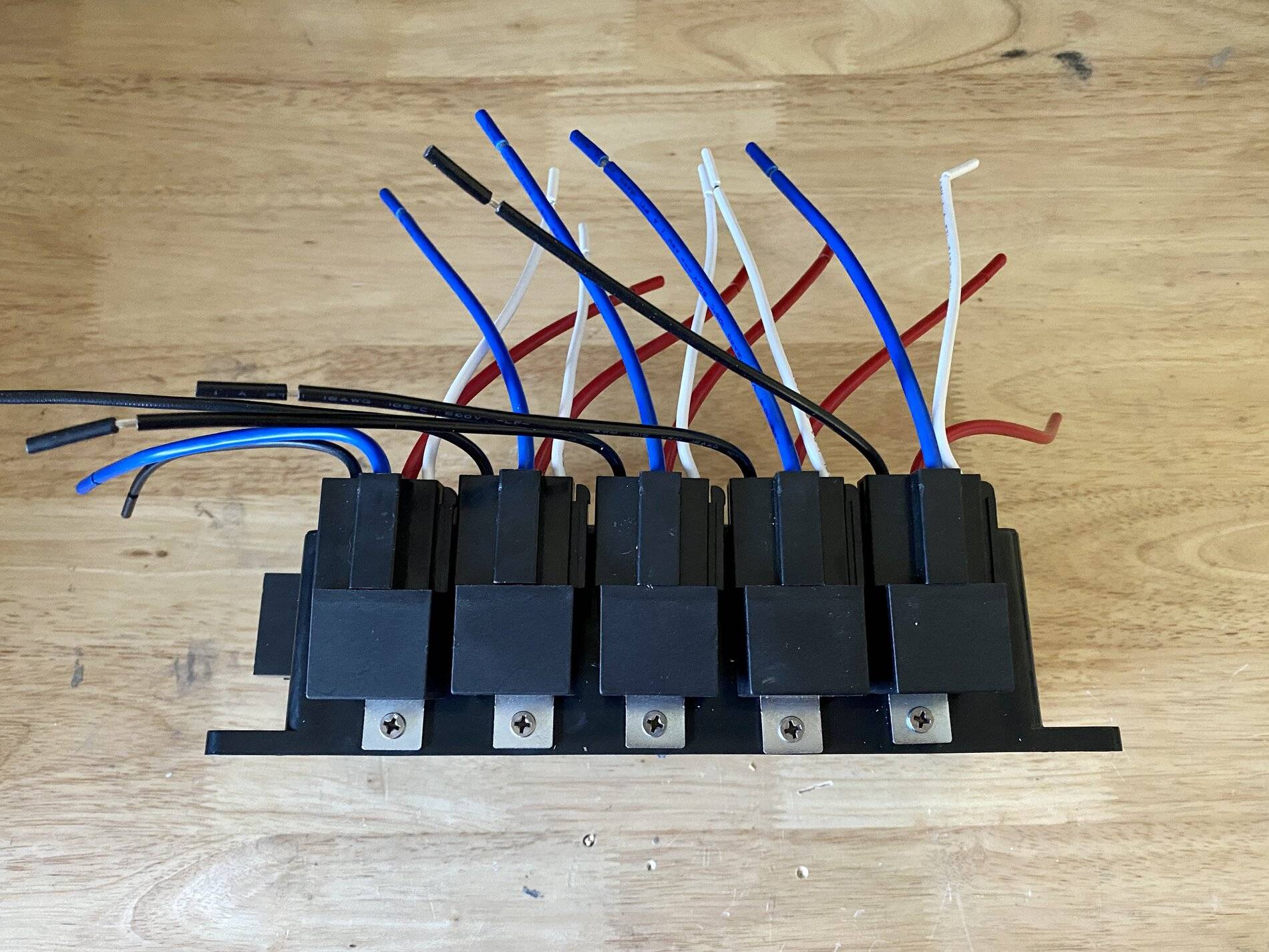
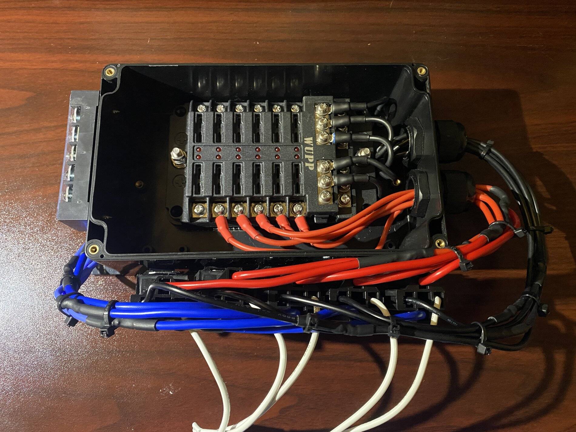
- First thing I did was mount all of the relays across the bottom of the project box as shown. To do this I eyeballed their location, marked the holes and drilled pilot holes before using some small zinc wood screws. In my case the screws penetrated the plastic so I ended up sealing these later with some clear silicone.

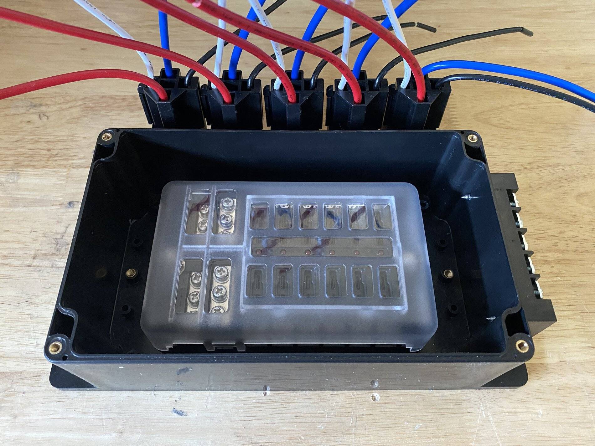
- I then mounted the fuse block in the center of the project box using high strength velcro
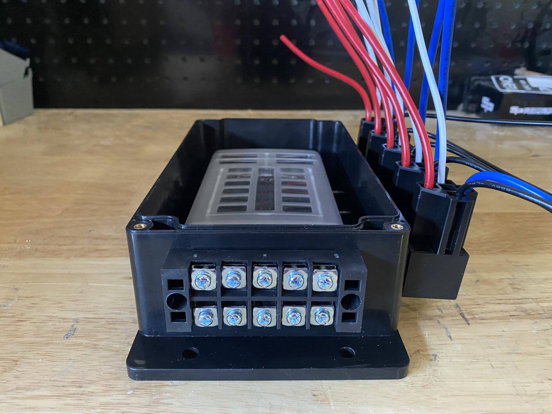
- From there I mounted a terminal block outside the project box using the same zinc wood screws
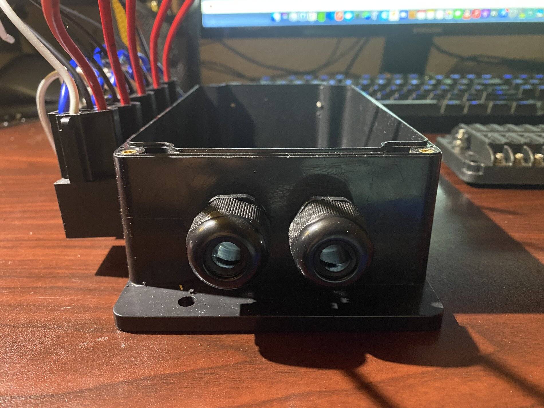
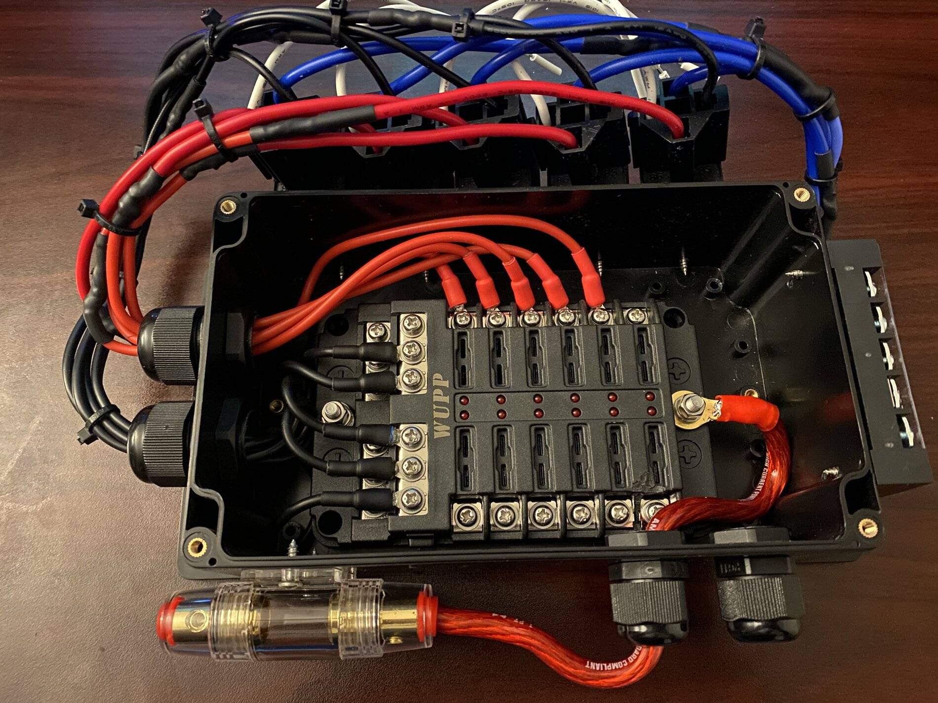
- Alright now that everything is mounted it was time to add waterproof cable connectors to the box. For this I drilled two main holes. I recommend using a small bit first as a pilot hole and then finish it with a hole saw or tapered drill bit. These will go opposite the side the terminal block.
- Now for the fun part. Wiring.
I had trouble finding relays that had long enough lead wires so I ended up extending each lead wire considerably. I measured the length of wire needed to get to the fuse block termination point from the end of the wire and then, cut, stripped and soldered the connections to the relay lead wires and finally added heatshrink around the exposed wire for protection.
You could probably use butt connectors and electrical tape for this step or find relays with long lead wires.
Lastly, I terminated each connection and again heatshrunk around the exposed wire.
Rinse and repeat for each lead wire except for the switched power in. I did terminate those lead wires with a connector so that I could plug/unplug switches as necessary.
Once this was done I went ahead and connected each wire from the relay harness to the fuse block and terminal block. It's worth mentioning that the ground wire location doesn't matter, but I did make sure to order the constant and relay power out 1-5 from left to right on both the fuse block and terminal block so that I could more easily trace things later on.
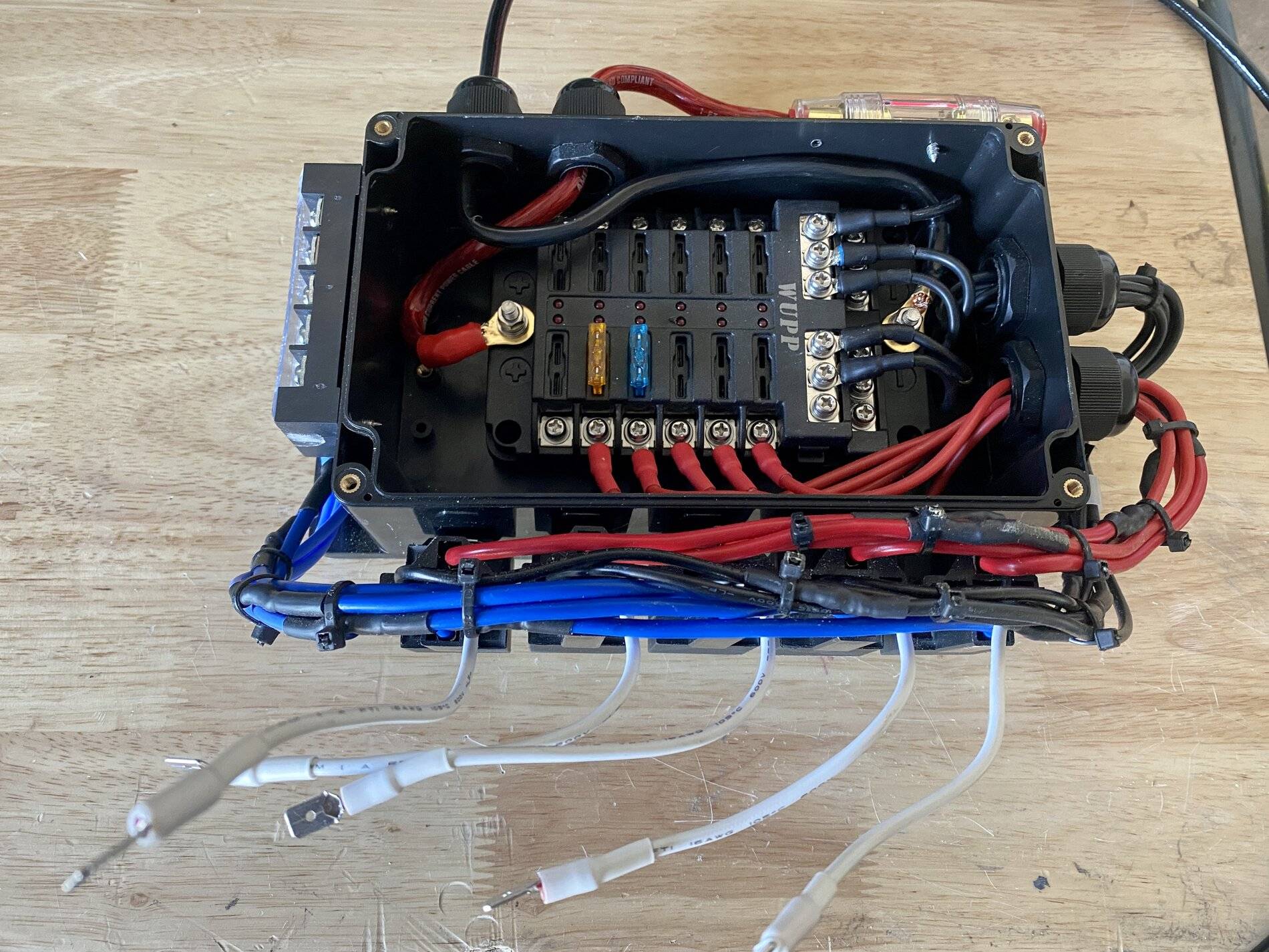
- The next step after everything is wired up is to drill and setup two more cable connectors for the main power and ground in. I used the same technique from before, but obviously positioned them on the top side of the project box, opposite the relay mounts.
Once that was done I then mounted the 100 amp inline fuse using the same screws mentioned before. As far as positioning goes, I eye balled everything and made sure to leave space for the wire bends.
- I then routed the main power cable (red) in through the cable connector and terminated it inside the box with a ring terminal. The opposite side connected to the inline fuse just needed to be stripped and inserted to the fuse connector.
- I did the same thing for the ground wire, but used ring terminals on both ends since one end would go to the battery and the other the fuse block.
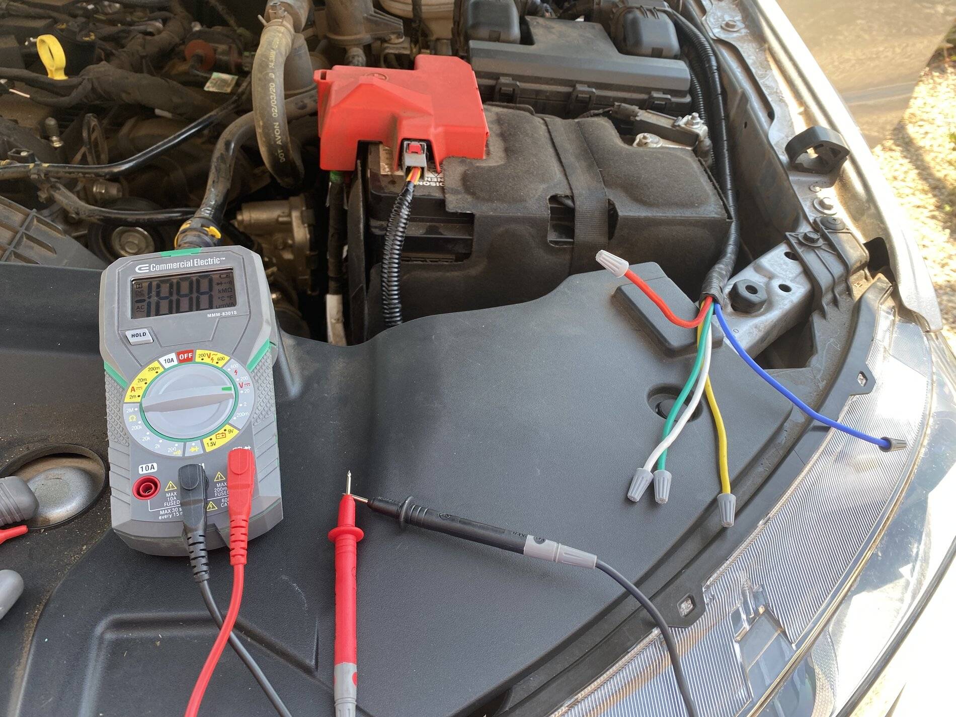
- After all this was done I used a multimeter to test my connections and make sure I had continuity across the fuse block. Once everything was confirmed working I cleaned it up a bit and used zip ties to hold back any excess cable.
- Outside of adding the fuses themselves, that was pretty much it for the relay fuse block build. Final product below.
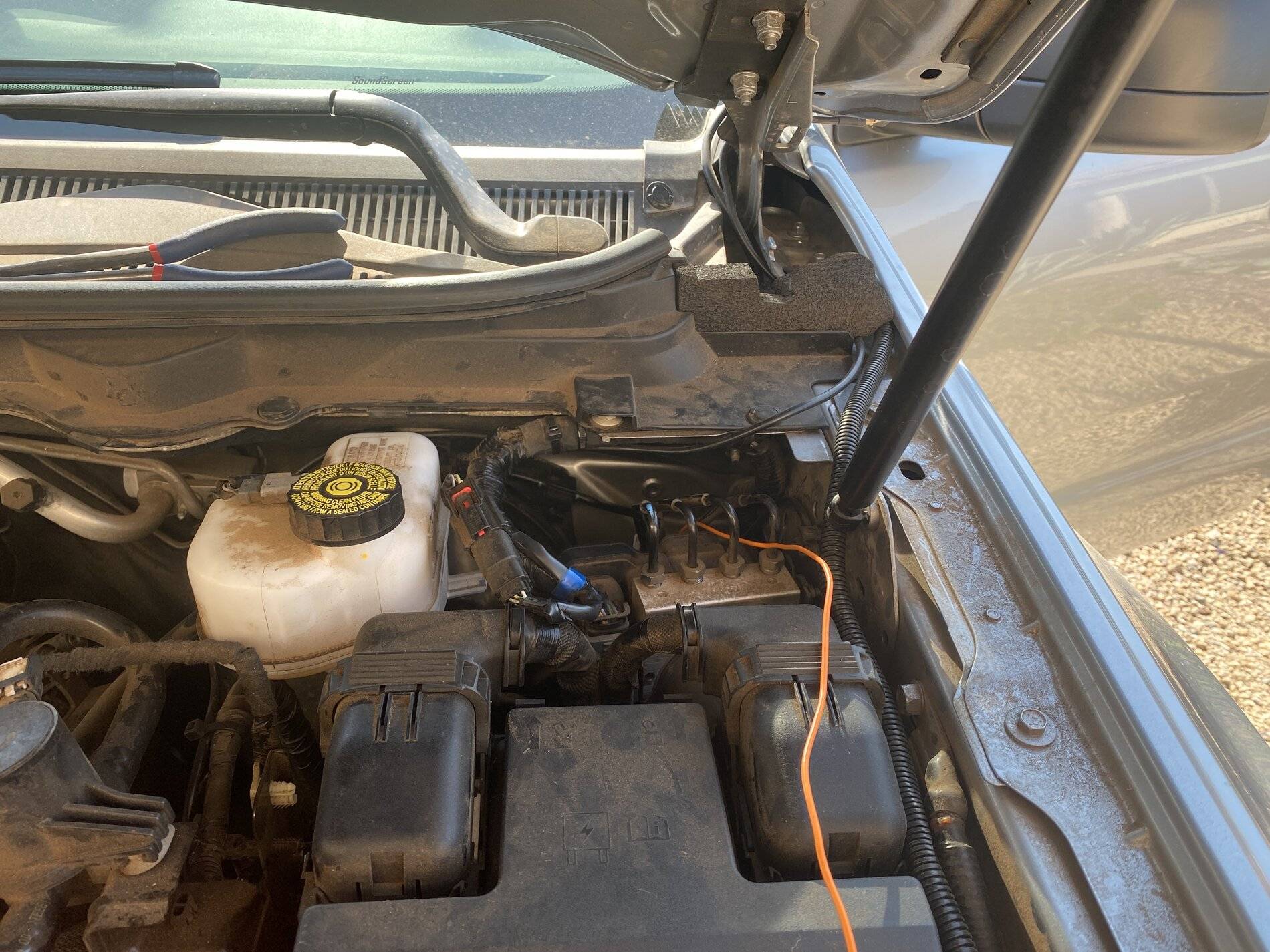
- Now for the install.
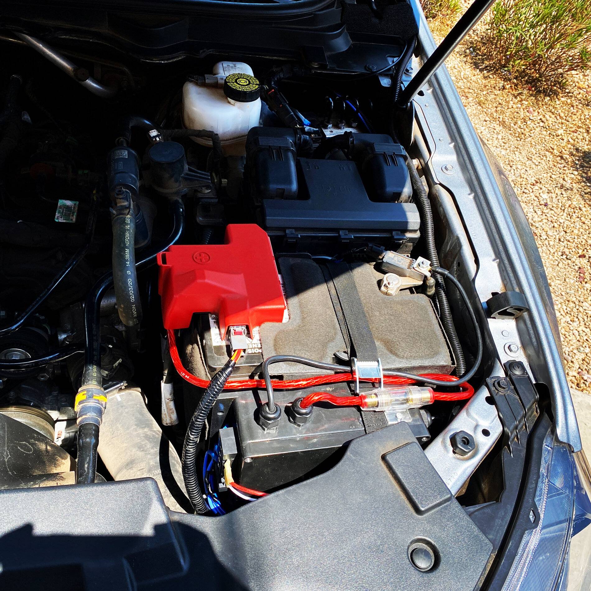
So I was originally thinking of mounting this thing across the core support below that large plastic shield that spans across the radiator, but I felt that would have been a pain to access. I opted to mount it in front of the battery using a lashing strap thats routed under the battery and across the relay box. This location with the strap is pretty secure. See below.
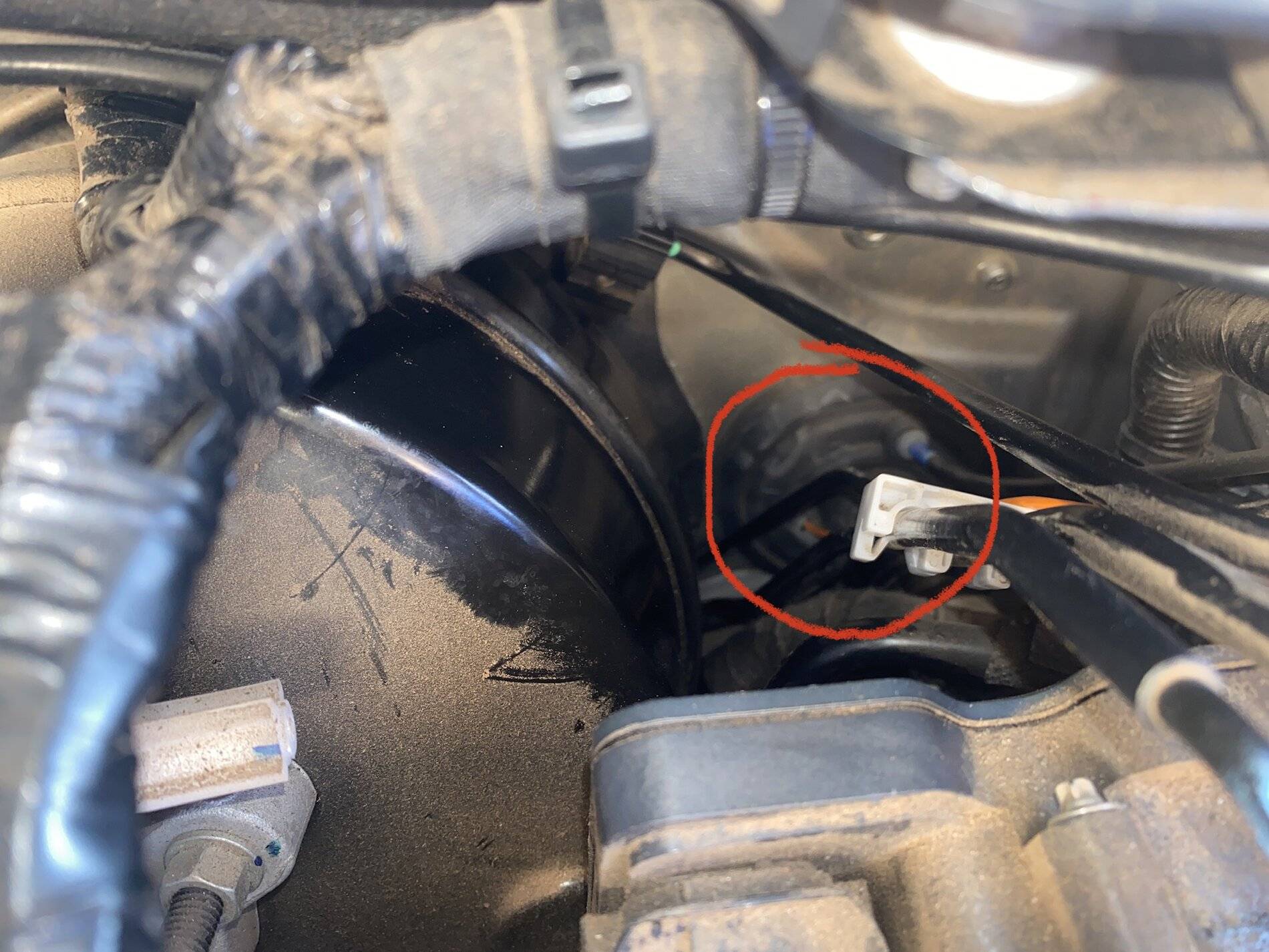
- The final step was routing the switched powered out wires from the cab to the relay fuse block. I ended going through a grommet located on the firewall using a wire feeding tool, but there's also a grommet under the driver side floor board that can be used.
With that done it was time to connect and test everything!

Final Product!


Sponsored
Last edited:

