Sponsored

Ford Ranger IV 2020 - No OBD connection

OP
OP

rokas

Active Member
Joined
May 27, 2026
Threads
1
Messages
38
Reaction score
3
Location
Lithuania
Vehicle(s)
Ford Ranger IV
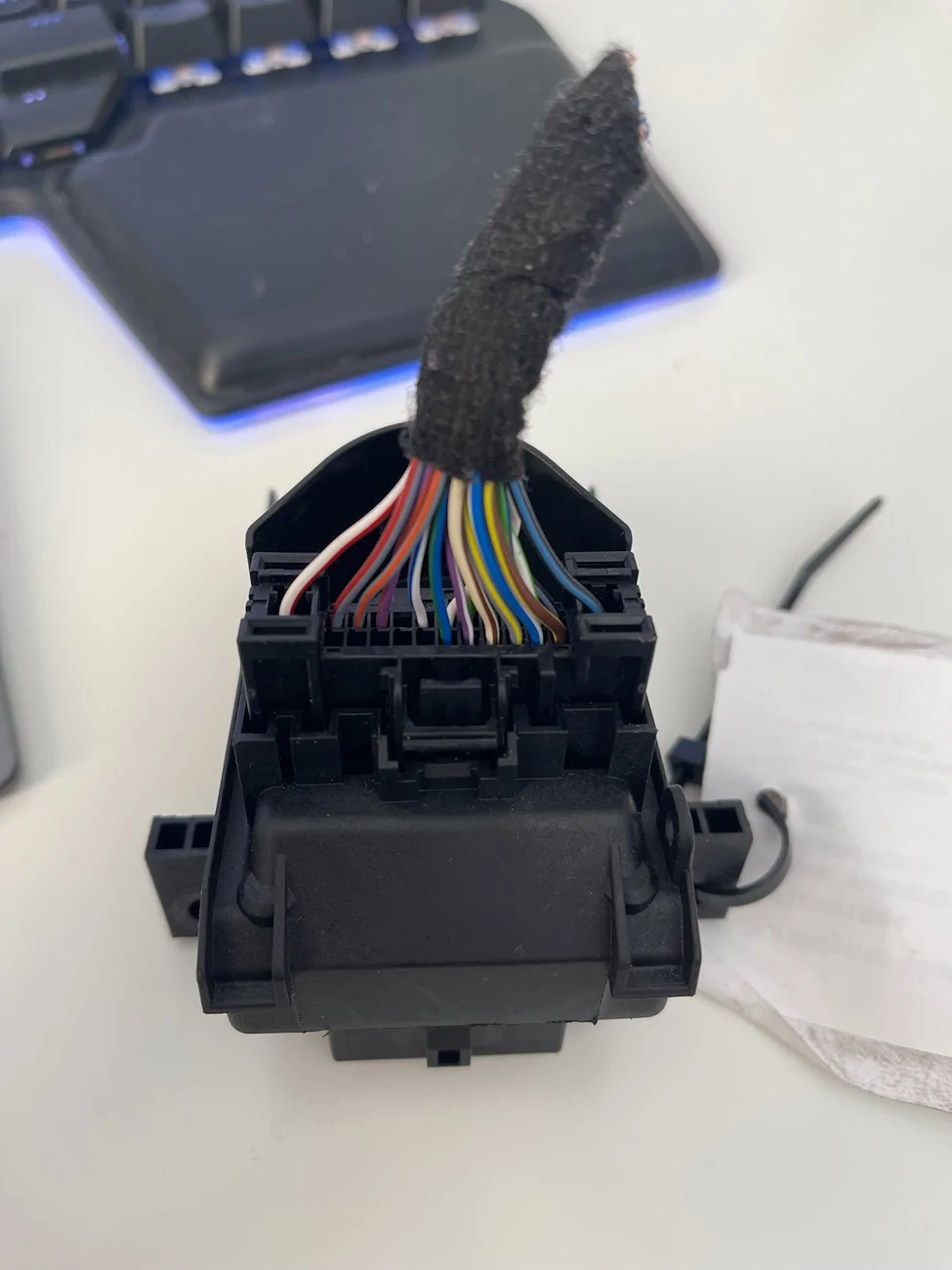
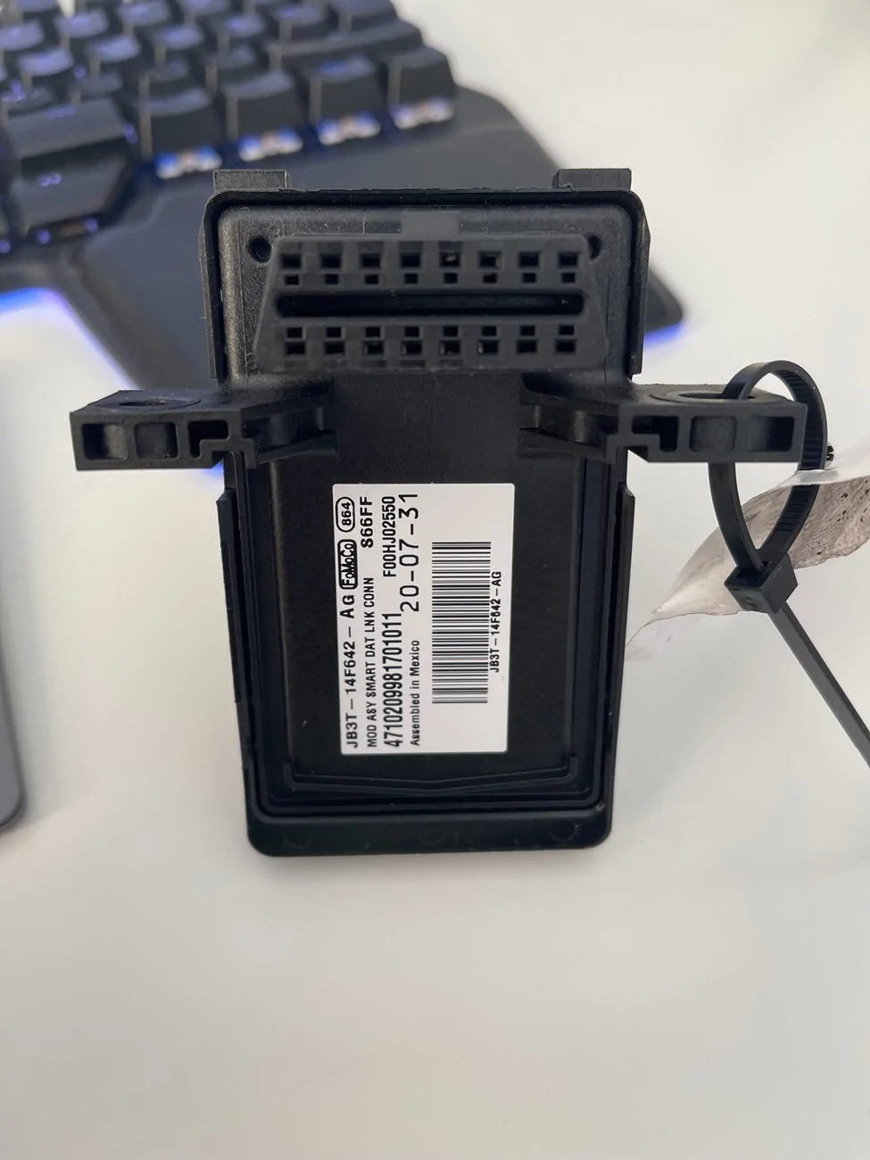
Just bought a used one. Same part number. Different wiring (from RHD Ranger). I will try to swap it.

Engine Installed? - yes

Do you have brake lights? - Push button start (requires brake pedal input) - one brake line is cut, but the car reacts to brake pedal pressing. I will double check the rear lights.

Do you know if the truck ever ran (after accident)? - no idea.

Was there any repairs done or was this simply bought at auction (totaled or as-is) salvaged title - bought from the dealer.

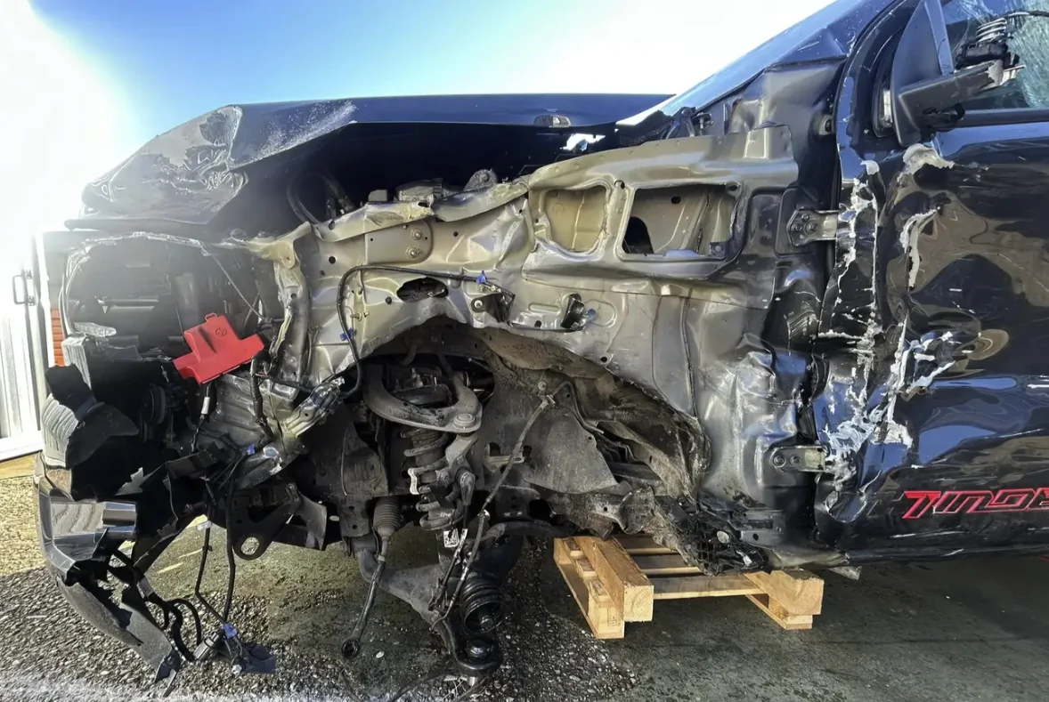
Exactly what was damaged - details of damage may reveal wire harness or fuse damage? - I will make more photos of BJB. Someone has definitely been there before.

If this is a 2.3 engine - when you open the door - do you hear the wastegate cycle? - 2.0 diesel. I will double check this too.

Have you checked every fuse and relay - PCM Power Relay / Starter Relay / Run Start Relay
are any of these clicking - when cycling the ignition or opening the door - This I will do today.

IPC - Full Power Up and any messages noted - will make more photos
APIM - Radio - Power Up and play music - yes
FCIM - Climate Controls work - blower motor - will double check, but I think yes
Does all the background lighting and exterior lighting work? - will double check.

Can you turn off the radio - yes
Turn signals work - yes

IMG_5630.webp


IMG_5629.webp


Screenshot 2026-05-30 at 11.39.09.webp
Sponsored

 
OP
OP

rokas

Active Member
Joined
May 27, 2026
Threads
1
Messages
38
Reaction score
3
Location
Lithuania
Vehicle(s)
Ford Ranger IV
Just got back from the garage. OBD works!

First things first: last time I measured the GWM CAN line voltages with the ignition ON and the module connected. All the lines showed voltages between 1.5V and 3.5V. This is where I made a mistake.

With the GWM disconnected, one CAN pair (GWM pins 22–23) started showing around 0.6V on both wires 💡

I started digging into where this CAN pair goes. I should mention that, for some reason, this truck has the tow bar removed and the wires cut. I don’t know why. There is no visible damage, but the wires were simply cut. Looking at the wiring diagram, I noticed that this CAN pair also goes through the Tow Control Module (TCM). After disconnecting this module, the pair started showing almost 0V at the GWM. I plugged in the OBD connector, and it connected!

Regarding the GWM, I’m still a bit surprised that it works, but it does — or I should say, it does its magic (SMART Data Link Connector after all).

One thing I should mention is that I was unable to connect to Forscan, but maybe something is wrong with my configuration. It says, “Unable to connect to the vehicle.” A standard OBD adapter connects and reads the ECUs. There are some codes from the BCM, but they are very generic. I’ll try to get Forscan working (it’s my first time using it, and there is no other Ford I can test it on right now).

Before noticing the voltage discrepancy, I also performed the checks you suggested. The AC works, and all the lights do too. The PCM and BCM wiring seems to be alright — everything appears to match according to the wiring diagram.

The next step is to get Forscan communicating with the truck. Then maybe it will become clearer why it does not start. Fuses and relays - checked.

Still, it’s a shame that I missed such an important detail about the 0.6V reading. Sorry and thank you very much for your help! I’ll update as soon as I gather more details.
 
Last edited:

RangerBill

Well-Known Member
First Name
Bob
Joined
Jun 8, 2022
Threads
3
Messages
1,619
Reaction score
2,149
Location
PA
Vehicle(s)
2019 Ford Ranger Lariat Super Crew FX4
Occupation
retired
Just got back from the garage. OBD works!

First things first: last time I measured the GWM CAN line voltages with the ignition ON and the module connected. All the lines showed voltages between 1.5V and 3.5V. This is where I made a mistake.

With the GWM disconnected, one CAN pair (GWM pins 22–23) started showing around 0.6V on both wires 💡

I started digging into where this CAN pair goes. I should mention that, for some reason, this truck has the tow bar removed and the wires cut. I don’t know why. There is no visible damage, but the wires were simply cut. Looking at the wiring diagram, I noticed that this CAN pair also goes through the Tow Control Module (TCM). After disconnecting this module, the pair started showing almost 0V at the GWM. I plugged in the OBD connector, and it connected!

Regarding the GWM, I’m still a bit surprised that it works, but it does — or I should say, it does its magic (SMART Data Link Connector after all).

One thing I should mention is that I was unable to connect to Forscan, but maybe something is wrong with my configuration. It says, “Unable to connect to the vehicle.” A standard OBD adapter connects and reads the ECUs. There are some codes from the BCM, but they are very generic. I’ll try to get Forscan working (it’s my first time using it, and there is no other Ford I can test it on right now).

Before noticing the voltage discrepancy, I also performed the checks you suggested. The AC works, and all the lights do too. The PCM and BCM wiring seems to be alright — everything appears to match according to the wiring diagram.

The next step is to get Forscan communicating with the truck. Then maybe it will become clearer why it does not start. Fuses and relays - checked.

Still, it’s a shame that I missed such an important detail about the 0.6V reading. Sorry and thank you very much for your help! I’ll update as soon as I gather more details.
So, unplugging the TCM restored OBD communications?
 
OP
OP

rokas

Active Member
Joined
May 27, 2026
Threads
1
Messages
38
Reaction score
3
Location
Lithuania
Vehicle(s)
Ford Ranger IV
Yes. The problematic CAN pair which showed 0.6V now shows close to 0V and this allows OBD to connect.
 

airline tech

Well-Known Member
Joined
Aug 24, 2022
Threads
28
Messages
4,473
Reaction score
8,545
Location
Midwest - KS
Vehicle(s)
2022 Ranger Lariat-Super Crew, Cactus Gray
Occupation
Aircraft Tech
Quick Ref for Module Coms:

These are for the US Version Ranger
The ROW Rangers will have a (TCM - Transmission Control Module) and its on the HS CAN 1 Bus that takes place of the integrated (PCM Control the US Version has)

MS CAN
-SODR
-SODL
-FCIM
-TRM
-RTM

HS CAN 1
-PCM
-OBD II
-APIM
-DCDC
-PAM
-BCM
-BEMB

HS CAN 2
-ATCM
-OCS
-CCM
-ABS
-TCU
-RCM
-PSCM
-SCCM
-GWM
-IPMA

HS CAN 3
-DSP
-ACM
-IPC

HS-CAN 4
-TCU
-APIM


Being that a generic tool can com - (What is the scan tool?)
I am looking for - is the tool (VIN#) read style that can pick up every module or it just reading ODD data
What modules will it read - using the quick ref above will tell us what can busses it sees.

As far as Forscan - I know as the versions progressed - the older adapters became problematic for connections - and the only one that appears not to have issues is the OBD Link EX or MX adaptors - so the ELM's, V-Linkers etc - owners have reported issues with them on the newer releases of Forscan

So to be clear - you have the new GWM installed and still had (No Com) and then disconnected the TRM (Trailer Module) and gained com.

Did this GWM - produce the pin to pin (passthrough) check you were missing form the OEM - GWM.?
Will these direct (continuity) to pins 17-20?

I had planed on - pulling mine out and checking (Curiosity) as this was something I cannot deduce will 100% certainty without actually checking - Is it supposed to be a direct feed or does the GWM switch the paths (internally) - when a scan tool is plugged in. But did not find the time for it.


airline tech

Well-Known Member
Joined
Aug 24, 2022
Threads
28
Messages
4,473
Reaction score
8,545
Location
Midwest - KS
Vehicle(s)
2022 Ranger Lariat-Super Crew, Cactus Gray
Occupation
Aircraft Tech
I think i may have some understanding - as i never really dug into this (specific) transition between the DLC & GWM

1. The Diag 1 & Diag 2 - we see on the diagrams are - Internal to the GWM (Only) these are the micro controller circuits that pick up the com data from all the busses

2. So the (no continuity) at pins 17-20 would be normal as the security com of the GWM opens the ports for communication for data.
The GWM is internally switching the logic board to read the data from pins 17-20 and producing the data to the DLC pins

3. When you test pins 6 and 14 from the front DLC - this is only testing the DLC for com to the GWM
This is testing the (Diag 1) & (Diag 2) bus - Totally Internal to the GWM
Pin 6 to Grd
Pin 14 to Grd
With Battery Disconnected - 60 Ohms

Powered
Pin 6 to Grd - Diag 1 Can High - 2.7 Volts
Pin 14 to Grd - Diag 1 Can Low - 2.3 Volts

Pin 3 to Grd - Diag 2 -Can High - 2.7 Volts
Pin 11 to Grd - Diag 2 -Can Low - 2.3 Volts

The key Point is - understanding the Ref to Diag 1 and Diag 2 are not the actual can busses this is misleading by how the wire diagrams depict it


Basically we need to look at this as a (Gateway Module) or router that is switching ports internally - I am sorry but this is a learning experience for me as well, since I do not do this professionally anymore and got out before scan tools diagnostics became a norm , so I have never really dug into the internal handling of the GWM and from what I gather I think my above theory of operation is correct - its not a direct connection as one would think.

I know there are some videos online that use - Can Bus (Breakout) boxes that may explain how it transitions better - I plan on watching to get a better understanding.
As you are really the first to have a full - no com issue and i have only used the data from scan tool com to pinpoint (where the issue) lies by seeing what coms are lost and what modules are producing a code.

Anyway - you are making some headway, that's a good sign
 
Last edited:

airline tech

Well-Known Member
Joined
Aug 24, 2022
Threads
28
Messages
4,473
Reaction score
8,545
Location
Midwest - KS
Vehicle(s)
2022 Ranger Lariat-Super Crew, Cactus Gray
Occupation
Aircraft Tech
So to dumb it down:

Diag 1 = HS1 (Network) - the GWM internally connects to the HS1 Can Bus
Diag 2 = HS2 - HS3 -HS4 and the MS Can Busses - also GWM internally connects to those busses

Pins 6 & 14 - Check Diag 1
Pins 3 & 11 - Check Diag 2

This only checks the com from the GWM to the DLC
 
OP
OP

rokas

Active Member
Joined
May 27, 2026
Threads
1
Messages
38
Reaction score
3
Location
Lithuania
Vehicle(s)
Ford Ranger IV
Quick Ref for Module Coms:

These are for the US Version Ranger
The ROW Rangers will have a (TCM - Transmission Control Module) and its on the HS CAN 1 Bus that takes place of the integrated (PCM Control the US Version has)

MS CAN
-SODR
-SODL
-FCIM
-TRM
-RTM

HS CAN 1
-PCM
-OBD II
-APIM
-DCDC
-PAM
-BCM
-BEMB

HS CAN 2
-ATCM
-OCS
-CCM
-ABS
-TCU
-RCM
-PSCM
-SCCM
-GWM
-IPMA

HS CAN 3
-DSP
-ACM
-IPC

HS-CAN 4
-TCU
-APIM


Being that a generic tool can com - (What is the scan tool?)
I am looking for - is the tool (VIN#) read style that can pick up every module or it just reading ODD data
What modules will it read - using the quick ref above will tell us what can busses it sees.

As far as Forscan - I know as the versions progressed - the older adapters became problematic for connections - and the only one that appears not to have issues is the OBD Link EX or MX adaptors - so the ELM's, V-Linkers etc - owners have reported issues with them on the newer releases of Forscan

So to be clear - you have the new GWM installed and still had (No Com) and then disconnected the TRM (Trailer Module) and gained com.

Did this GWM - produce the pin to pin (passthrough) check you were missing form the OEM - GWM.?
Will these direct (continuity) to pins 17-20?

I had planed on - pulling mine out and checking (Curiosity) as this was something I cannot deduce will 100% certainty without actually checking - Is it supposed to be a direct feed or does the GWM switch the paths (internally) - when a scan tool is plugged in. But did not find the time for it.
I used a standard ELM327 with the Car Scanner Android app. There is a fault, U0100(87), on the BCM and DCDC, which I think prevents the truck from starting. I'm not sure if every Ranger has a 230V socket, but this one does. There might be something related to the DCDC after all, because at least the CAN wires between the BCM and PCM passed the continuity check. It was quite late, so I stopped further inspection.

Regarding the Forscan adapter, I have a V-Linker. I will try to downgrade the software.

Answering the GWM question — no, I used the original GWM that came with the truck, and yes, after disconnecting the Trailer Tow Module located under the driver's seat, the MS1 CAN line showed close to 0V, and OBD communication worked with the ELM adapter connected. I will inspect the GWM’s internal operation further on my next visit to the garage.
 

airline tech

Well-Known Member
Joined
Aug 24, 2022
Threads
28
Messages
4,473
Reaction score
8,545
Location
Midwest - KS
Vehicle(s)
2022 Ranger Lariat-Super Crew, Cactus Gray
Occupation
Aircraft Tech
GWM - showing the transceivers - that the wiring diagram leaves out, i knew it had the terminating resistors inside, but did not realized or pay attention to the detail that there was an extra set of (resistors) inside for Diag 1 and Diag 2


GWM Transciever.webp
 
OP
OP

rokas

Active Member
Joined
May 27, 2026
Threads
1
Messages
38
Reaction score
3
Location
Lithuania
Vehicle(s)
Ford Ranger IV
GWM - showing the transceivers - that the wiring diagram leaves out, i knew it had the terminating resistors inside, but did not realized or pay attention to the detail that there was an extra set of (resistors) inside for Diag 1 and Diag 2


GWM Transciever.webp
That’s some interesting stuff happening inside the GWM. If I understand correctly, cutting off the MS1 CAN line did not break anything because the transceivers collect and pass the data. If I had cut off, for example, HS1, that would not have worked.
 

airline tech

Well-Known Member
Joined
Aug 24, 2022
Threads
28
Messages
4,473
Reaction score
8,545
Location
Midwest - KS
Vehicle(s)
2022 Ranger Lariat-Super Crew, Cactus Gray
Occupation
Aircraft Tech
I used a standard ELM327 with the Car Scanner Android app. There is a fault, U0100(87), on the BCM and DCDC, which I think prevents the truck from starting. I'm not sure if every Ranger has a 230V socket, but this one does. There might be something related to the DCDC after all, because at least the CAN wires between the BCM and PCM passed the continuity check. It was quite late, so I stopped further inspection.

Regarding the Forscan adapter, I have a V-Linker. I will try to downgrade the software.

Answering the GWM question — no, I used the original GWM that came with the truck, and yes, after disconnecting the Trailer Tow Module located under the driver's seat, the MS1 CAN line showed close to 0V, and OBD communication worked with the ELM adapter connected. I will inspect the GWM’s internal operation further on my next visit to the garage.
The (AC Outlet) is from the DC/AC - the DC/DC is a separate module, both the BCM and DCDC sit on HS1

So we know that the DCDC is pushing power out as you have voltage on Pin 24 (GWM) that's is what provides it. (VBAT)
So if you look at the wiring diagram you will also see (VPWR) - this uses Ign signal to power out to such various items - such as the Rear Camera - (Will the rear camera show - when in reverse?)
 
OP
OP

rokas

Active Member
Joined
May 27, 2026
Threads
1
Messages
38
Reaction score
3
Location
Lithuania
Vehicle(s)
Ford Ranger IV
Rear camera works when in reverse. Checked last time.
 

airline tech

Well-Known Member
Joined
Aug 24, 2022
Threads
28
Messages
4,473
Reaction score
8,545
Location
Midwest - KS
Vehicle(s)
2022 Ranger Lariat-Super Crew, Cactus Gray
Occupation
Aircraft Tech
for me at this point
I think the PCM is not powering up
Unless you are able to read codes or connect and the scan tool read the VIN from the PCM

I would also get the OBD-EX adaptor - this has proven to work without issues with Forscan, this way you will have a better chance of getting communication to the truck and get a much better view of what is happening, either that or a high end scan tool such as Autel or Topdon, Snap-On.

Can you take a pic or identify what connector that was cut off, so we can see what wires are in it and if this is affecting the no start issue.

When you looked at the diagram - you will note (see) that the MS-Can runs back to the taillights and then routes back forward to the TRM on a separate wire run, this is why disconnecting the TRM at least cured part of the problem
 
OP
OP

rokas

Active Member
Joined
May 27, 2026
Threads
1
Messages
38
Reaction score
3
Location
Lithuania
Vehicle(s)
Ford Ranger IV
Very valuable insights. Power to the PCM and VIN scan are the first checks I will do, since from what I understand the DC-DC converter might be good.

I did not take a picture of the instrument cluster. It shows all the information (gear, mileage, fuel level), but perhaps the PCM is not needed for this information.

OBD-EX adapter — noted.

I will take a picture of the cut connector. I am out of words to thank you for your help!
 

airline tech

Well-Known Member
Joined
Aug 24, 2022
Threads
28
Messages
4,473
Reaction score
8,545
Location
Midwest - KS
Vehicle(s)
2022 Ranger Lariat-Super Crew, Cactus Gray
Occupation
Aircraft Tech
If you have 4WD a quick test:
Can you switch from 2 High to 4 Hi or Lo
If yes the PCM Power Relay is closing.
Key On - Test

Also even if you do not have 4WD , check fuse 19 in the BJB with key on (PSCM) fuse feed- if power is here - the Run Start Relay is closing.

This will give some direction on what is happening- verify power to these points.
Sponsored


Top