rokas
Active Member
- Thread starter
- #1
Hey,
I’ve got a 2020 Ford Ranger and I’m troubleshooting a CAN/OBD issue.
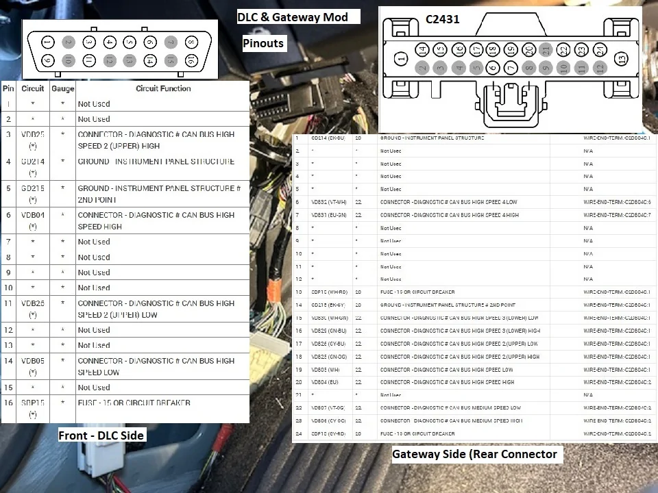
At the OBD port, pins 6 and 14 show close to 0 V, and I measure about 120 Ω resistance between them.
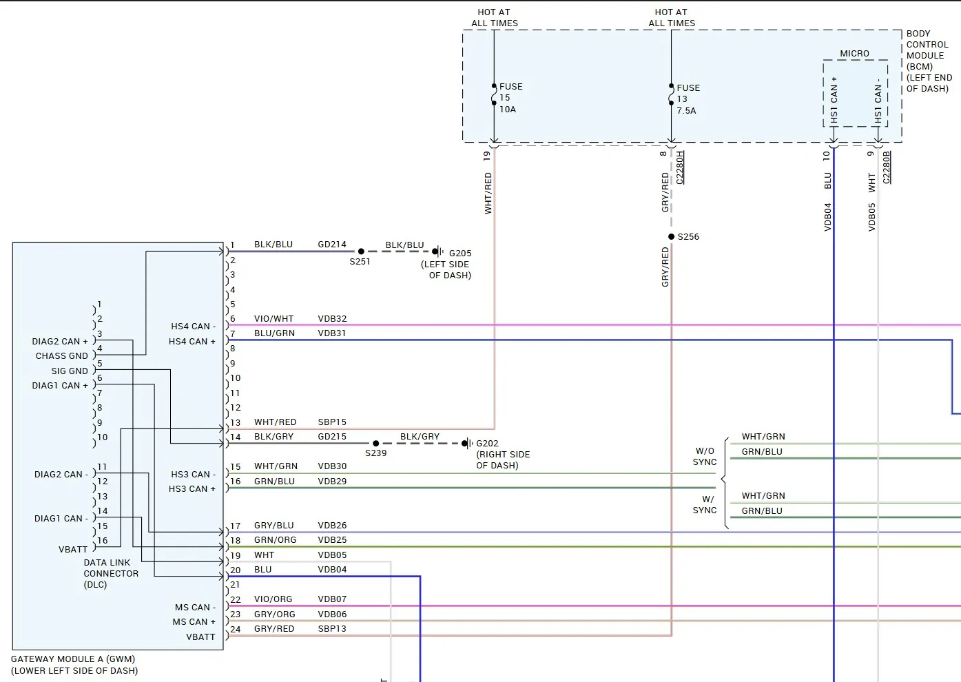
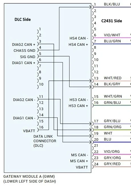
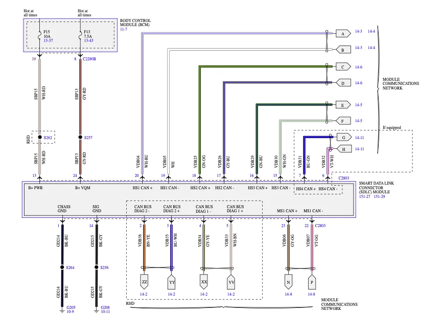
I started digging by disconnecting the SDLC module and checking continuity with a multimeter. I found continuity between SDLC pins 4 & 5 and OBD pins 6 & 14.
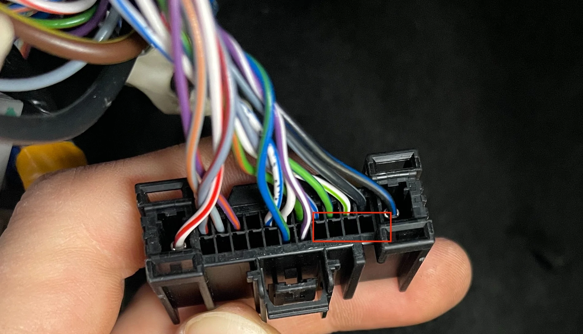
However, what confuses me is this: on my truck, the SDLC connector does not seem to have wires in positions 2–5 at all — only pins 6 & 7 on the first row are populated. Mine is a left-hand-drive Ranger.
If there are physically no wires in the SDLC positions that should correspond to OBD pins 6 and 14, how can OBD pins 6 and 14 still have continuity / a CAN connection? Is there a different routing on LHD Rangers, or am I misunderstanding the wiring diagram?
SDLC wiring diagram attached.
One more thing to add. I bought this truck after accident. Truck does not start and I have no history of it.
Any help would be much appreciated!

I’ve got a 2020 Ford Ranger and I’m troubleshooting a CAN/OBD issue.
At the OBD port, pins 6 and 14 show close to 0 V, and I measure about 120 Ω resistance between them.
I started digging by disconnecting the SDLC module and checking continuity with a multimeter. I found continuity between SDLC pins 4 & 5 and OBD pins 6 & 14.
However, what confuses me is this: on my truck, the SDLC connector does not seem to have wires in positions 2–5 at all — only pins 6 & 7 on the first row are populated. Mine is a left-hand-drive Ranger.
If there are physically no wires in the SDLC positions that should correspond to OBD pins 6 and 14, how can OBD pins 6 and 14 still have continuity / a CAN connection? Is there a different routing on LHD Rangers, or am I misunderstanding the wiring diagram?
SDLC wiring diagram attached.
One more thing to add. I bought this truck after accident. Truck does not start and I have no history of it.
Any help would be much appreciated!
Sponsored
Last edited: