airline tech
Well-Known Member
- Joined
- Aug 24, 2022
- Threads
- 28
- Messages
- 4,469
- Reaction score
- 8,545
- Location
- Midwest - KS
- Vehicle(s)
- 2022 Ranger Lariat-Super Crew, Cactus Gray
- Occupation
- Aircraft Tech
The fuse circuit has a minimum of 4 points of failure, and each one adversely affects all 4 systems. There appears to be no redundancy. Several questions come to mind...
1 - Do each of these systems fail gracefully when power is lost to the circuit?
2 - Is the internal pressure relief valve mechanical (pressure spring)
- Cabin Heater (Coolant Pump)
- Trans Fluid Heater Coolant Cont Valve
- Turbo-Charger By-Pass Valve
- Variable Oil Pump (Oil Press Cont Solenoid Valve)
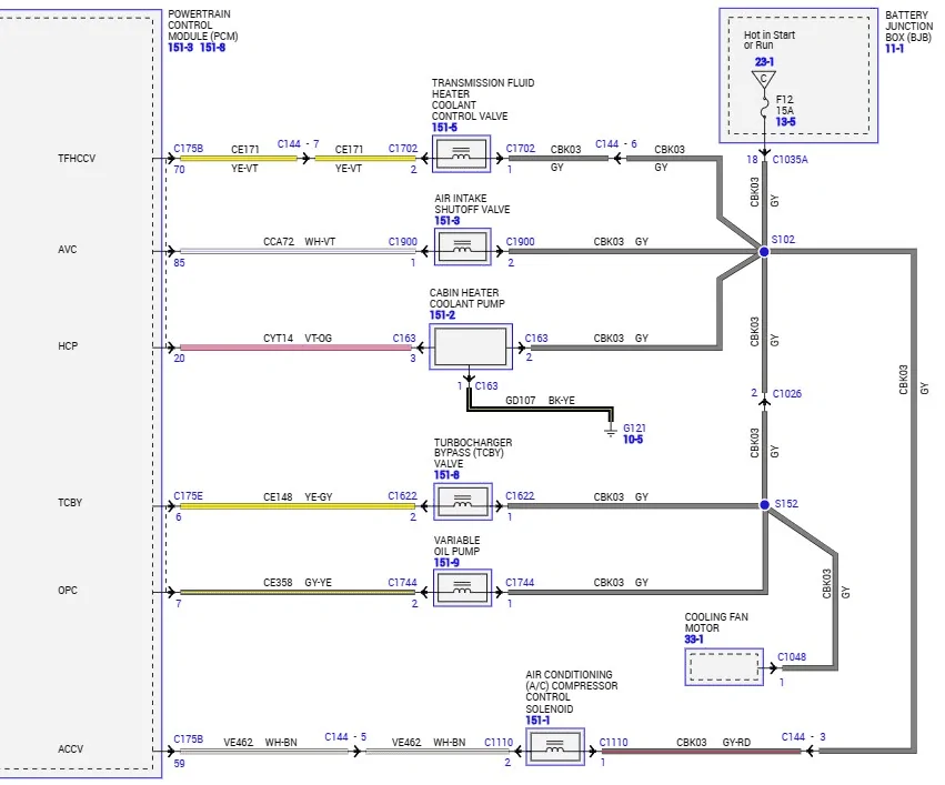
Ok, did some digging for the circuits that are tied into the Fan Clutch:
This is what I found:
Now keep in mind that all of these circuits will only drop if the Fan Clutch wire harness shorts out and possibly blows the fuse.
This is only showing the power feed side, you also have the VREF (5-Volt) circuit not depicted here. I found the diagram that only has this circuit as I missed some things on the complete engine control circuit.
1. The Cabin Heater (Coolant Pump) - Only active with ASS, provides coolant flow with cold outside temps while in ASS is active to continue flow (with electric) coolant pump to take place of the water pump with engine not running. ---So most likely ASS will disable.
2. Trans Fluid Heater Coolant Cont Valve - Normally open, closed with 12-volt power applied.
This valve allows or by-passes coolant through the Tran Oil Cooler for heat transfer tranny fluid to the coolant.
3. Turbo-Charger By-Pass Valve: No Fail safe found but assume that it will not work with no power.
4. Fan Clutch, now if the fan is not rotating or low airflow across the radiator, then the cooling system has a failsafe mode. (2) modes open/closed loop failure
This puts engine into LIMP mode, reduced engine power and limits to 3,000 RPM and has the ability to limit to 800 RPM, it can also deactivate (2) cylinders. (Overheat Protection)
5. Air Intake Shut-Off Valve (Note: diagram is nomenclated wrong) this is the Aspirator Valve.
This is normally closed and when powered it allows vacuum to be added to the brake booster, if the booster is sensing low vacuum.
6. AC Compressor Control Solenoid: Ac Compressor will not run, so no AC
7. Oil Pressure Cont Solenoid: Lengthy Description (Copy/Paste)
No Fail-Safe mode found for this, but the Oil Press sensor will read a low pressure and put engine into LIMP Mode (Power Reduced) if this solenoid drastically drops oil pressure.
You will still have an Oil Pump, mechanically driven, you just will not get the variable control out of it, so it should be full pressure (unaltered)
Update:
I dug into the Pinpoint test for the solenoid, and with it disconnected, (same as power drop with blown fuse) Oil Press should rise by 40 PSI, so this would be the fail-safe.
Unclear which system we have in the Ranger as it is not clear
Oil Pressure Control Solenoid
A conventional mechanical oil pump is connected to and driven by the crankshaft and produces oil
pressure proportional to engine speed, The Variable Oil Pump (VOP) is capable of varying its
output oil pressure as necessary. The Oil Pressure Control Solenoid, also known as Variable Oil
Pump Control (VOPC), is a solenoid that controls the output of the Variable Oil Pump.
There are two VOP systems currently being used. They are (1) a two-stage pressure system and
(2) continuous variable pressure system. The two-stage pressure system provides two pressure
modes, low and high. The continuous variable pressure system directly controls output pressure
based on commands from the Variable Oil Pump Control (VOPC) solenoid.
There are currently two different hardware configurations currently in use for these two systems.
They are (1) Variable Displacement Oil Pump (VDOP) which controls the oil pump directly and (2)
Active Oil Filter Adapter (AOFA) which controls the oil drain system.
The VDOP adjusts the pump’s displacement using a moveable slide that controls the filling and
draining of the oil in the reservoir via two ports in the pump. The oil pressure control solenoid
controls the amount of oil filling by partially or completely opening and closing the passage. The
AOFA consists of a conventional oil pump and a separate oil bypass line. The oil pressure control
solenoid opens and closes a bypass line which allows oil to drain back to the sump. The VDOP
can be configured to operate as both a two-stage pressure system as well as a continuous
variable pressure system; however, the AOFA can only be used for a two-state pressure system.
Regardless of pump and system types, the actual solenoid hardware is identical.
Sponsored
Last edited: