Zaph
Well-Known Member
- Thread starter
- #1
Component selection and overall design concept
This is going into a 301A non-B&O equipment group package. I've settled on the behind the seat space for a few reasons, roughly similar to the area the B&O sub would go, and I will be custom building the enclosure to make the most use of the area. I've chosen this area for a couple reasons - 1st, I actually use the under seat storage for stuff like jumper cables and a rescue kit, and 2nd, I'm not a fan of horizontally mounted subwoofers.
Horizontally mounted subwoofers work fine for a while. Then they start have an issue with something called "cone sag". Subwoofers have an excursion spec called Xmax. From the factory they start out +/- the same distance. Over time, the weight of the cone, suspension and voice coil causes the the coil to sag in the magnet gap, making the excursion non-linear. For example what was +/- 8mm this year becomes +4mm/-12mm next year. Then power handling becomes more limited and distortion crops up. There's more to it, but for subwoofers, vertical mounting is always better.
I don't need a lot of additional output so for me a single 8" higher output sub will do the trick. However I'll configure it so I get the most out of it, more on that in the simulations below. I do not look at power handling ratings at all because they are generally not realistic. I look at Thiele Small parameters. Most important for a small enclosure size is a smallish Vas, and then I want a somewhat low Fs and reasonable Qts. Then after that based on experience I'll make a mental guess on how much power I *really* need. It's not going to be that much power.
The system will get line level signal off the rear speakers. The front and rear speakers will continue to run full range off the OEM amplifier and the subwoofer will blend in on the low end to fill and enhance the missing bottom 1.5 octaves.
My chosen components are:

Kicker - CompRT 8" dual voice coil, 2 ohms per coil, model 43CWRT82
The key features I need in this are low profile, decent Xmax, low Vas. It cost $128 on Amazon.

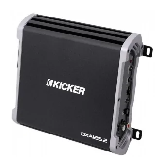
Kicker - DXA125.2 two channel amp, model 43DXA1252
The key features I need in this are the subsonic filter in case I go vented, line level inputs, adjustable low pass filter, and the 40hz bass boost may be useful. It cost $90 on Amazon.
There are a lot of options out there. My range of expertise is in home audio, but home audio drivers rarely have the needed Thiele Small parameters optimized for smaller enclosures. Kicker's "Solo Baric" series is known for working well in smaller enclosures. It's a play on the old term "isobaric" which used two woofers face to face in an enclosure to get by with half the size. However I shy away from square drivers or anything non-circular as they are generally higher distortion due to uneven cone loading.
This Kicker subwoofer is "rated" at 600 watts maximum power. That is a laughable power rating, though typical for the car audio industry. You will see how the DXA125.2, which is rated at 60 watts x 2 @ 2 ohms is a pretty good match for this woofer if I use each channel to drive each 2 ohm coil. If I wanted I could series the coils to 4 ohms and bridge the amp, which is functionally the same configuration, however there are some technical benefits to driving the coils separately so I will do that.
I'll end this section with saying that I have very little respect for car audio. All the BS and lack of knowledge in the industry kind of makes me sick. Combine that with the worst listening room known to man, the worst speaker enclosures known to man, and most of the time I don't even bother trying. But sometimes I do anyway and I want a little more bass extension and output in my truck, so here I go. :\ Tests up next.
This is going into a 301A non-B&O equipment group package. I've settled on the behind the seat space for a few reasons, roughly similar to the area the B&O sub would go, and I will be custom building the enclosure to make the most use of the area. I've chosen this area for a couple reasons - 1st, I actually use the under seat storage for stuff like jumper cables and a rescue kit, and 2nd, I'm not a fan of horizontally mounted subwoofers.
Horizontally mounted subwoofers work fine for a while. Then they start have an issue with something called "cone sag". Subwoofers have an excursion spec called Xmax. From the factory they start out +/- the same distance. Over time, the weight of the cone, suspension and voice coil causes the the coil to sag in the magnet gap, making the excursion non-linear. For example what was +/- 8mm this year becomes +4mm/-12mm next year. Then power handling becomes more limited and distortion crops up. There's more to it, but for subwoofers, vertical mounting is always better.
I don't need a lot of additional output so for me a single 8" higher output sub will do the trick. However I'll configure it so I get the most out of it, more on that in the simulations below. I do not look at power handling ratings at all because they are generally not realistic. I look at Thiele Small parameters. Most important for a small enclosure size is a smallish Vas, and then I want a somewhat low Fs and reasonable Qts. Then after that based on experience I'll make a mental guess on how much power I *really* need. It's not going to be that much power.
The system will get line level signal off the rear speakers. The front and rear speakers will continue to run full range off the OEM amplifier and the subwoofer will blend in on the low end to fill and enhance the missing bottom 1.5 octaves.
My chosen components are:
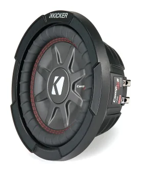
Kicker - CompRT 8" dual voice coil, 2 ohms per coil, model 43CWRT82
The key features I need in this are low profile, decent Xmax, low Vas. It cost $128 on Amazon.
Kicker - DXA125.2 two channel amp, model 43DXA1252
The key features I need in this are the subsonic filter in case I go vented, line level inputs, adjustable low pass filter, and the 40hz bass boost may be useful. It cost $90 on Amazon.
There are a lot of options out there. My range of expertise is in home audio, but home audio drivers rarely have the needed Thiele Small parameters optimized for smaller enclosures. Kicker's "Solo Baric" series is known for working well in smaller enclosures. It's a play on the old term "isobaric" which used two woofers face to face in an enclosure to get by with half the size. However I shy away from square drivers or anything non-circular as they are generally higher distortion due to uneven cone loading.
This Kicker subwoofer is "rated" at 600 watts maximum power. That is a laughable power rating, though typical for the car audio industry. You will see how the DXA125.2, which is rated at 60 watts x 2 @ 2 ohms is a pretty good match for this woofer if I use each channel to drive each 2 ohm coil. If I wanted I could series the coils to 4 ohms and bridge the amp, which is functionally the same configuration, however there are some technical benefits to driving the coils separately so I will do that.
I'll end this section with saying that I have very little respect for car audio. All the BS and lack of knowledge in the industry kind of makes me sick. Combine that with the worst listening room known to man, the worst speaker enclosures known to man, and most of the time I don't even bother trying. But sometimes I do anyway and I want a little more bass extension and output in my truck, so here I go. :\ Tests up next.
Sponsored
")