JDG
Active Member
- Joined
- Aug 13, 2021
- Threads
- 5
- Messages
- 40
- Reaction score
- 93
- Location
- Conshohocken, PA
- Vehicle(s)
- 2021 Ranger Lariat Tremor, 2016 Fiesta ST
- Thread starter
- #1
I have been interested in getting some of the tremor upfitter switches to function while the vehicle is not on for quite some time. Through some digging and testing in the vehicle, I have determined how it can be done and have implemented it in my 2021 Ford Ranger Tremor. Since I have received a lot of benefit from this forum, I thought it was about time I provide some benefit on a topic I have seen come up occasionally among other members.
I have seen a number of posts regarding these upfitter switches as well as wiring diagrams posted that are not accurate. What I have learned through my research and testing is that the Ranger Tremor Switches are identical to those used on the 2017-2022 Ford F-250 and thus have the capability of being wired in different configurations. The switch assembly part number (for reference) is HC3Z-13D730-AA.
I was also able to determine that the relay coils in the upfitter switch relay enclosure (in the engine bay) are always hot which makes this modification possible by only performing wiring in the passenger compartment.
Here are the configurations available:

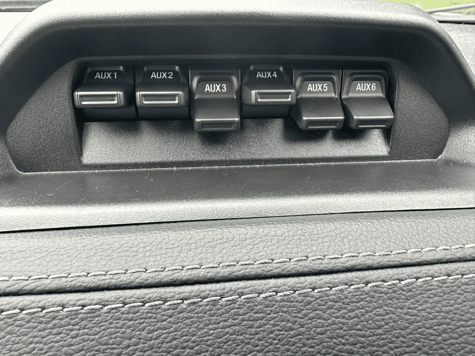
In my case, to safely remove the 12-pin connector, I also had to remove the switch assembly from the trim piece. This required unscrewing all (4) T-25 torx screws from the backside. Below is a figure of the pin numbering for the molex connector as well as the wiring diagram for the F-250.

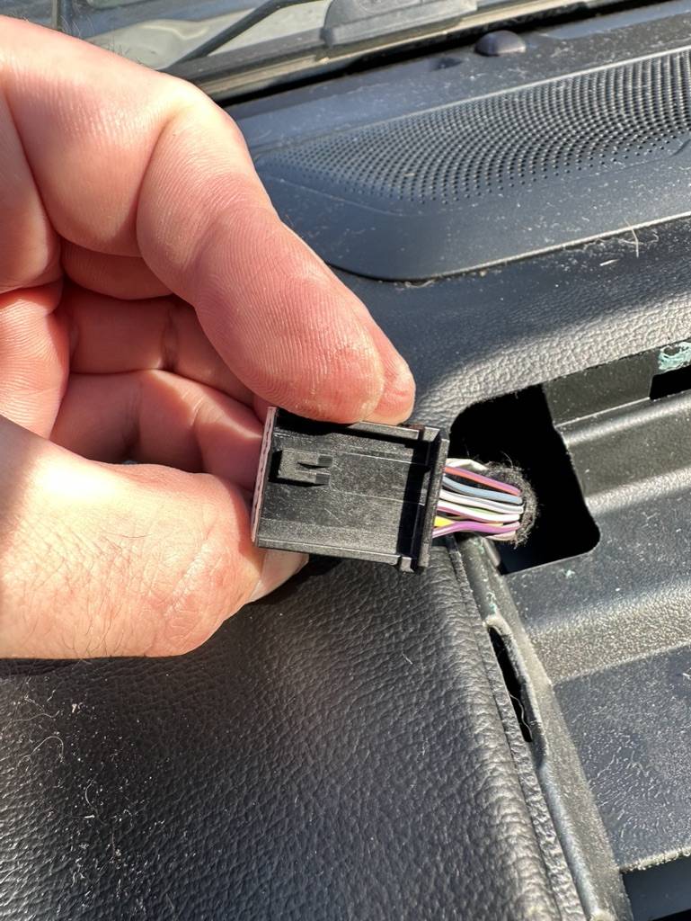
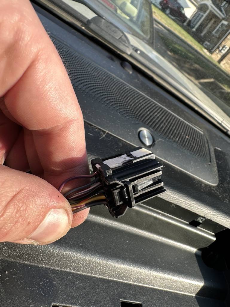
From the F-250 upfitter wiring diagram (and from testing), we know that pins 5 and 11 supply switched 12v power to the upfitter switches with pin 5 supplying switches 5-6 and pin 11 supplying switches 1-4. In the case of my vehicle, the switched +12v power supplying the switches was a yellow with violet wire for both pin 5 and 11.
So we know that we need to create a new wire that is always hot for pin 5 and/or pin 11 depending on which configuration we would like:
I opted to also purchase some spare molex connectors (P/N 34729-0120) in case I damaged the connector during this project. I ended up damaging the original molex connector on the truck while removing pin 5 and had to swap all the factory wires to the new connector I had purchased.
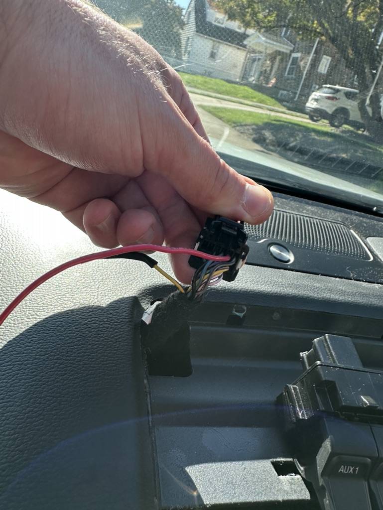
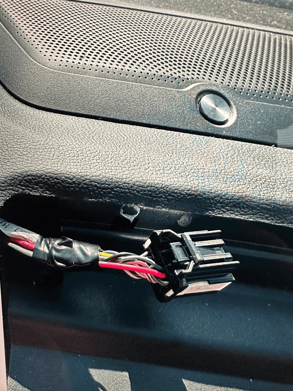
Final Result in Upfitter Switch Area (The red wire is my newly installed wire in the pin 5 position that is wired into an always on circuit in the fuse panel)

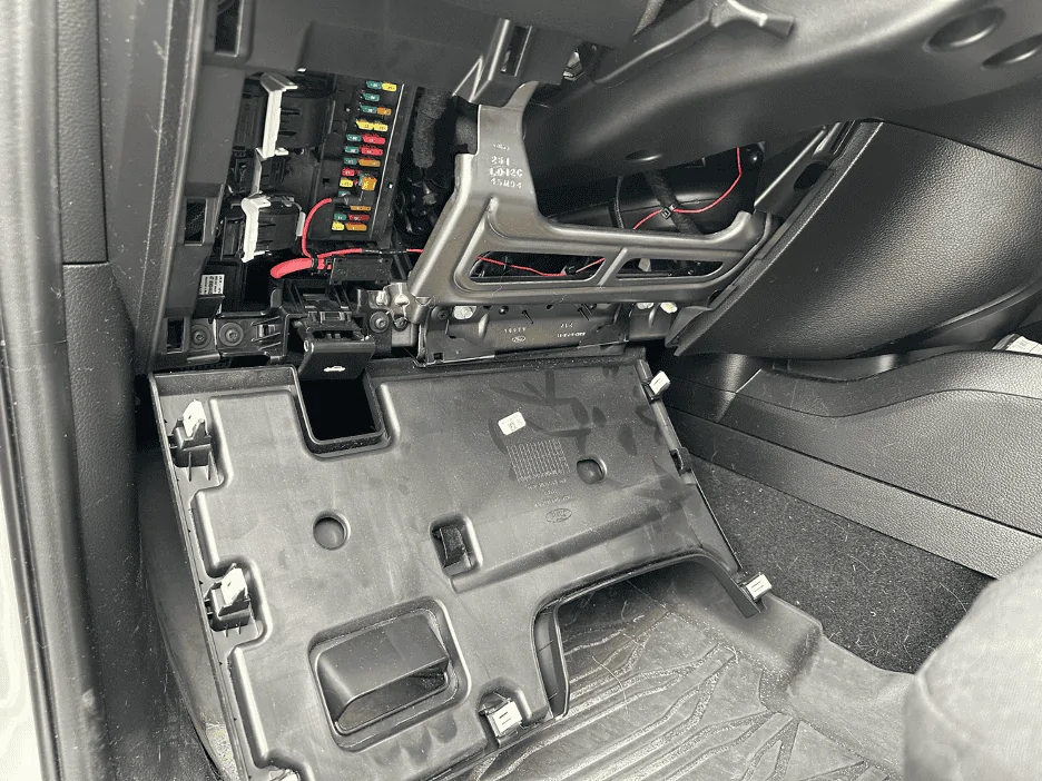
There is a simple path for our new wire(s) from the location of the upfitter switches to the passenger compartment fuse panel on the driver side under the steering wheel. You only need to remove the fuse panel cover to gain access to the area needed to run/secure the new wire(s). You will then need to connect the new wire(s) to a fuse tap. The fuses in the passenger compartment are Micro-II fuses.
I opted to install a 5A fuse into the fuse tap to stay consistent with the fuse sizing in the F-250 for this wiring. I also opted to use Fuse 16 for my always on power source. Note the orientation of the fuse tap is important during installation.
A great guide on the passenger compartment fuses can be found here: https://www.ranger5g.com/forum/threads/passenger-compartment-fuses.14754/
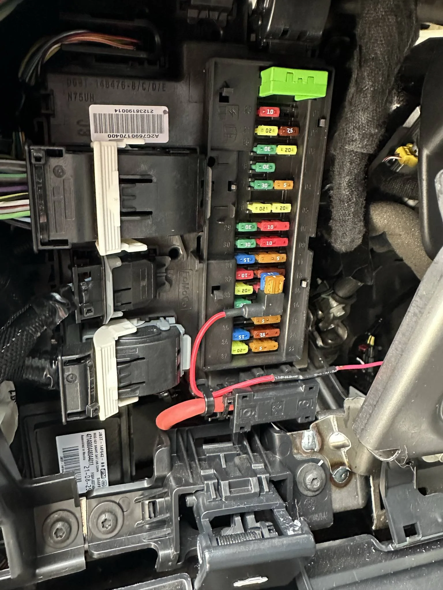
Final Result in Driver Footwell


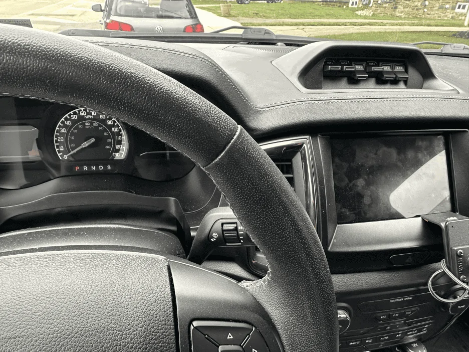
Note Switch 5 & 6 are on (and lit) with vehicle powered off:
Parts Needed
As always with anything that I post, anything you do to your vehicle is at your own risk. I will not be held liable if you do damage to your vehicle while following this guide. I will also not be held liable if you are hurt or worse due to this modification.
Please let me know if you have any questions. I hope this can be helpful for some of you.
I have seen a number of posts regarding these upfitter switches as well as wiring diagrams posted that are not accurate. What I have learned through my research and testing is that the Ranger Tremor Switches are identical to those used on the 2017-2022 Ford F-250 and thus have the capability of being wired in different configurations. The switch assembly part number (for reference) is HC3Z-13D730-AA.
I was also able to determine that the relay coils in the upfitter switch relay enclosure (in the engine bay) are always hot which makes this modification possible by only performing wiring in the passenger compartment.
Here are the configurations available:
- Wire all 6 switches to be functional with the vehicle off
- Wire switches 1-4 to be functional with the vehicle off
- Wire switches 5-6 to be functional with the vehicle off (This is what I implemented on my truck)
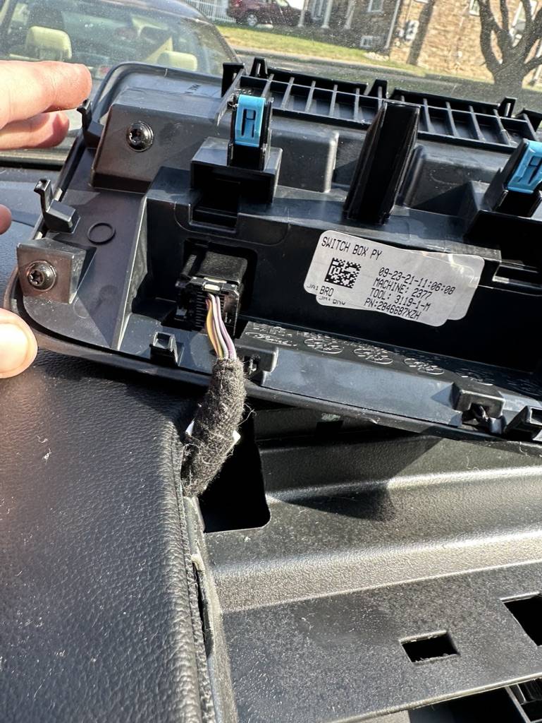
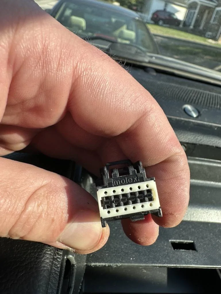
In my case, to safely remove the 12-pin connector, I also had to remove the switch assembly from the trim piece. This required unscrewing all (4) T-25 torx screws from the backside. Below is a figure of the pin numbering for the molex connector as well as the wiring diagram for the F-250.
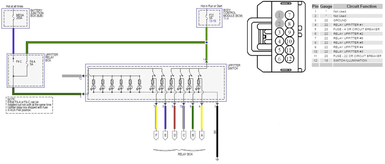
From the F-250 upfitter wiring diagram (and from testing), we know that pins 5 and 11 supply switched 12v power to the upfitter switches with pin 5 supplying switches 5-6 and pin 11 supplying switches 1-4. In the case of my vehicle, the switched +12v power supplying the switches was a yellow with violet wire for both pin 5 and 11.
So we know that we need to create a new wire that is always hot for pin 5 and/or pin 11 depending on which configuration we would like:
- Wire all 6 switches to be functional with the vehicle off (wire always on +12v to pin 5 and pin 11)
- Wire switches 1-4 to be functional with the vehicle off (wire always on +12v to pin 11 only)
- Wire switches 5-6 to be functional with the vehicle off (wire always on +12v to pin 5 only)
I opted to also purchase some spare molex connectors (P/N 34729-0120) in case I damaged the connector during this project. I ended up damaging the original molex connector on the truck while removing pin 5 and had to swap all the factory wires to the new connector I had purchased.
Final Result in Upfitter Switch Area (The red wire is my newly installed wire in the pin 5 position that is wired into an always on circuit in the fuse panel)
There is a simple path for our new wire(s) from the location of the upfitter switches to the passenger compartment fuse panel on the driver side under the steering wheel. You only need to remove the fuse panel cover to gain access to the area needed to run/secure the new wire(s). You will then need to connect the new wire(s) to a fuse tap. The fuses in the passenger compartment are Micro-II fuses.
I opted to install a 5A fuse into the fuse tap to stay consistent with the fuse sizing in the F-250 for this wiring. I also opted to use Fuse 16 for my always on power source. Note the orientation of the fuse tap is important during installation.
A great guide on the passenger compartment fuses can be found here: https://www.ranger5g.com/forum/threads/passenger-compartment-fuses.14754/
Final Result in Driver Footwell
Note Switch 5 & 6 are on (and lit) with vehicle powered off:
Parts Needed
- Molex Pins (P/N 34803-3212): https://www.mouser.com/ProductDetail/Molex/34803-3212-Loose-Piece?qs=8%2Bu/V6/T1OoXFsCHl9DAmA==
- Molex Connector (Not necessary but good to have in case you damage the existing connector removing the pins) (P/N 34729-0120): https://www.mouser.com/ProductDetail/Molex/34729-0120?qs=1/kFHMS5B/iNFA1IC6Ywrw==
- 20AWG Red Wire (~6' Length): Ideally GXL Automotive specification
- Micro-II Fuse Tap; I used Bussmann BP-HHTR-RP: https://www.autozone.com/electrical...sories/p/bussmann-circuit-fuse-tap/547344_0_0
- Micro-II 5A Fuse
- Butt connector to connect new wire to fuse tap
- Heat Shrink tubing
- Zip Ties
- Panel removal tools for switch trim removal
- T-25 Torx bit or driver (bolts are only hand tight)
- Molex pin removal tool or small pick
- Crimper for new molex pin(s) - I used a Delphi Packard pin crimper that I have had for a decade and it worked great
- Butt connector crimper
- Wire stripper
- Butane torch or lighter for heat shrink tubing
- Dielectric grease (for easier molex pin installation in connector)
- Fish tape (Not necessary in my case but could be helpful for wire routing)
- Needle nosed pliers for fuse removal
As always with anything that I post, anything you do to your vehicle is at your own risk. I will not be held liable if you do damage to your vehicle while following this guide. I will also not be held liable if you are hurt or worse due to this modification.
Please let me know if you have any questions. I hope this can be helpful for some of you.
Sponsored
")
