Sponsored

Running a circuit through the fuse box: Is it possible?

airline tech

Well-Known Member
Joined
Aug 24, 2022
Threads
28
Messages
4,464
Reaction score
8,542
Location
Midwest - KS
Vehicle(s)
2022 Ranger Lariat-Super Crew, Cactus Gray
Occupation
Aircraft Tech
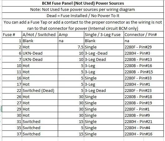
I played some today, now here is some information regarding fused power that may help.
Note: As I noted any (Not Used) power sources in the BJB (Battery Junction Box) - Engine Bay does not appear to have any contacts installed (so useless) and just blank holes.

However - The BCM (fuse panel) is mostly circuited with power at the fuses and to the connector ports (on the BCM). This is for (per the wiring diagrams) Not Used fuses.
The connectors do not have the wiring or contact pin on the connectors, so you can add a (Tapped) Fuse off of the fuse itself, or for a cleaner wire run (add a contact pin & wire at the specified connector) for that fused power source.

I just updated this today and checked with a meter, I only pulled one connector just as a confirmation the wire is not installed on the connector, however the pin is installed on the BCM port, just waiting for something to be connected. I have been wanting to do this for some time and finally got it done.

Note: for the individual contact pin P/N's they will vary depending on wire gauge, as they are not listed at pin location, so have to use a similar wire gauged P/N and cross it over to that pin location. It can be done but time consuming

BCM Not Used Power Sources.webp


And this was my previous guide (for switched power sources only)

Switched Fused Power Guide.webp


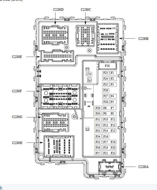
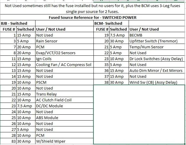
BCM - Panel Reference - Note: The longer fuses in the collum are the (3-Legged Fuses) single source power feeding both legs (sides) of the fuse.

BCM Fuse Panel.webp
Sponsored

 
OP
OP
Oingoboingoagogo
Joined
Oct 14, 2024
Threads
2
Messages
23
Reaction score
6
Location
USA
Vehicle(s)
2020 Ford Ranger Lariat
Thank you everyone for your responses. I am grateful for the activity, however with this number of responses I do not have time to address everyone.

To save others time, I'd like to reiterate that I am looking for unused, unpowered circuits running between a fuse box in the cab and the fuse box in the engine bay. A few users have suggested doing a fuse tap for power—a useful suggestion and something I am considering doing, but to be clear, I am not looking for a power source in this thread.

To all who pointed out my mistake regarding the Trigger 6, thank you. I did not realize it's a wireless switching system. Very cool. If I had 5 more ooga horns I'd just get that. ? Actually, this makes me think about rigging up a wireless switch with a microcontroller, Arduino or something. But seems like a lot of trouble just to avoid fishing a wire...

@OFC Ranger Thanks for the clarification re: Tremor electrical. I gather you know your stuff.:thumbsup:

@treeranger Thank you for the encouragement!

@airline tech That's a super useful study for getting power off of the fuse boxes. Thank you for the info. Just to be clear though, you have not found any unpowered, tappable circuits running between the BCM and the BJB, right? You mention "dead"contacts in the BCM, but on the other side the "Engine Bay does not appear to have any contacts installed." Are you saying there is a wire that goes there, but no fuse-contacts on the end of the wire where it meets the BJB? Or, that there are slots on the BJB with no wire running to them at all?
 

airline tech

Well-Known Member
Joined
Aug 24, 2022
Threads
28
Messages
4,464
Reaction score
8,542
Location
Midwest - KS
Vehicle(s)
2022 Ranger Lariat-Super Crew, Cactus Gray
Occupation
Aircraft Tech
You are missing how the Truck is wired.
The BJB -(Engine Bay Fuse Box) is a 2-sided box (Upper & Lower)
Below that Box - Is a High-Current Fuse Box
In that box - Contains 3 Fuses (4 if Tremmor Package)
1 Mega-Fuse in that box is a 125 Amp Fuse - this fuse feeds the BCM Power & Related Fuses
All the Fuses on the BCM are secondary to that 125-Amp Fuse - Follow under that fused power.
The BCM fuses - that are listed in the above post, supply circuit protection to the various circuits, so you will have wiring coming off the BCM fuses feeding into the Engine Bay and Cabin (USED)

There are ONLY 2 wire circuits that tie directly from BJB to the BCM - They are for the Lighting Circuits (USED)
and 1 wire circuit from the High Current Fuse Box to the BCM - 125 Amp (USED)

The BJB and BCM are not old school fuse boxes - they are circuit board boxes

The BJB - circuit board - has (Not Used) fuse locations on it - they are just empty holes and no contact pins in the fuse locations. So, if you want to tap for power here a fuse tap MUST be used on a (USED) Circuit

The BCM - circuit board is different as it also has - NOT USED fuses, Fuse 1 is a blank hole, no fuse installed and no contact pins in the slots.
For the rest of the fuses, they are installed with contact pins, and the circuit board is internally wired from the fuse location to the (Connector-Connection) point - that's are far as it goes.
The connector is NOT WIRED for that pin, so if you want to tap a NOT USED fuse you have to add a TAP or add a Contact Pin and draw power there.

For the Fuses that are DEAD - The Fuse is installed but I do not see any Contact Pins in the slots and was not able to read any power on the fuse - Run or Accy, wiring diagram lists the pins as not used

There is NOT any unused wire circuits that run from the BJB to the BCM
These are the ONLY power feeds INTO the BCM

C2280A = 125 Amp Fuse Input from High Current Fuse Box
C2280B - Pin 17 = Input Power from the DC/DC Convertor (Fused from a 50-Amp Fuse (High Current Fuse Box)
C2280B - Pin 21 -(BJB) Fuse 67 - 50-Amp (Lighting Circuits)
C2280B - Pin 22 (BJB) Fuse 62 - 50-Amp (Lighting Circuits)

Thats all the power feeds into the BCM all USED

Now you also have circuits that run into the cabin from the BJB and do not route to the BCM but again they are all (USED) They are the higher current users in the cabin - Powerpoints, HORN etc.

For what you want - you MUST run some wiring from the cabin to external
Keep in mind that there are multiple avenues for routing wiring, various plugs
and if you pull the drivers floorboard carpeting, you have some more not depicted here

1729206518209-zx.webp
 

Msfitoy

Well-Known Member
First Name
Sid
Joined
Mar 5, 2019
Threads
67
Messages
9,197
Reaction score
28,379
Location
North Carolina
Vehicle(s)
2019 Ranger, 2003 MINI Cooper S, 2021 Honda CT125
Occupation
NWO Robot Polisher
Vehicle Showcase
1
You are missing how the Truck is wired.
The BJB -(Engine Bay Fuse Box) is a 2-sided box (Upper & Lower)
Below that Box - Is a High-Current Fuse Box
In that box - Contains 3 Fuses (4 if Tremmor Package)
1 Mega-Fuse in that box is a 125 Amp Fuse - this fuse feeds the BCM Power & Related Fuses
All the Fuses on the BCM are secondary to that 125-Amp Fuse - Follow under that fused power.
The BCM fuses - that are listed in the above post, supply circuit protection to the various circuits, so you will have wiring coming off the BCM fuses feeding into the Engine Bay and Cabin (USED)

There are ONLY 2 wire circuits that tie directly from BJB to the BCM - They are for the Lighting Circuits (USED)
and 1 wire circuit from the High Current Fuse Box to the BCM - 125 Amp (USED)

The BJB and BCM are not old school fuse boxes - they are circuit board boxes

The BJB - circuit board - has (Not Used) fuse locations on it - they are just empty holes and no contact pins in the fuse locations. So, if you want to tap for power here a fuse tap MUST be used on a (USED) Circuit

The BCM - circuit board is different as it also has - NOT USED fuses, Fuse 1 is a blank hole, no fuse installed and no contact pins in the slots.
For the rest of the fuses, they are installed with contact pins, and the circuit board is internally wired from the fuse location to the (Connector-Connection) point - that's are far as it goes.
The connector is NOT WIRED for that pin, so if you want to tap a NOT USED fuse you have to add a TAP or add a Contact Pin and draw power there.

For the Fuses that are DEAD - The Fuse is installed but I do not see any Contact Pins in the slots and was not able to read any power on the fuse - Run or Accy, wiring diagram lists the pins as not used

There is NOT any unused wire circuits that run from the BJB to the BCM
These are the ONLY power feeds INTO the BCM

C2280A = 125 Amp Fuse Input from High Current Fuse Box
C2280B - Pin 17 = Input Power from the DC/DC Convertor (Fused from a 50-Amp Fuse (High Current Fuse Box)
C2280B - Pin 21 -(BJB) Fuse 67 - 50-Amp (Lighting Circuits)
C2280B - Pin 22 (BJB) Fuse 62 - 50-Amp (Lighting Circuits)

Thats all the power feeds into the BCM all USED

Now you also have circuits that run into the cabin from the BJB and do not route to the BCM but again they are all (USED) They are the higher current users in the cabin - Powerpoints, HORN etc.

For what you want - you MUST run some wiring from the cabin to external
Keep in mind that there are multiple avenues for routing wiring, various plugs
and if you pull the drivers floorboard carpeting, you have some more not depicted here

1729206518209-zx.jpg
I don't what you just said but if I were OP, I'd just give the whole idea up...
 
OP
OP
Oingoboingoagogo
Joined
Oct 14, 2024
Threads
2
Messages
23
Reaction score
6
Location
USA
Vehicle(s)
2020 Ford Ranger Lariat
You are missing how the Truck is wired.
The BJB -(Engine Bay Fuse Box) is a 2-sided box (Upper & Lower)
Below that Box - Is a High-Current Fuse Box
In that box - Contains 3 Fuses (4 if Tremmor Package)
1 Mega-Fuse in that box is a 125 Amp Fuse - this fuse feeds the BCM Power & Related Fuses
All the Fuses on the BCM are secondary to that 125-Amp Fuse - Follow under that fused power.
The BCM fuses - that are listed in the above post, supply circuit protection to the various circuits, so you will have wiring coming off the BCM fuses feeding into the Engine Bay and Cabin (USED)

There are ONLY 2 wire circuits that tie directly from BJB to the BCM - They are for the Lighting Circuits (USED)
and 1 wire circuit from the High Current Fuse Box to the BCM - 125 Amp (USED)

The BJB and BCM are not old school fuse boxes - they are circuit board boxes

The BJB - circuit board - has (Not Used) fuse locations on it - they are just empty holes and no contact pins in the fuse locations. So, if you want to tap for power here a fuse tap MUST be used on a (USED) Circuit

The BCM - circuit board is different as it also has - NOT USED fuses, Fuse 1 is a blank hole, no fuse installed and no contact pins in the slots.
For the rest of the fuses, they are installed with contact pins, and the circuit board is internally wired from the fuse location to the (Connector-Connection) point - that's are far as it goes.
The connector is NOT WIRED for that pin, so if you want to tap a NOT USED fuse you have to add a TAP or add a Contact Pin and draw power there.

For the Fuses that are DEAD - The Fuse is installed but I do not see any Contact Pins in the slots and was not able to read any power on the fuse - Run or Accy, wiring diagram lists the pins as not used

There is NOT any unused wire circuits that run from the BJB to the BCM
These are the ONLY power feeds INTO the BCM

C2280A = 125 Amp Fuse Input from High Current Fuse Box
C2280B - Pin 17 = Input Power from the DC/DC Convertor (Fused from a 50-Amp Fuse (High Current Fuse Box)
C2280B - Pin 21 -(BJB) Fuse 67 - 50-Amp (Lighting Circuits)
C2280B - Pin 22 (BJB) Fuse 62 - 50-Amp (Lighting Circuits)

Thats all the power feeds into the BCM all USED

Now you also have circuits that run into the cabin from the BJB and do not route to the BCM but again they are all (USED) They are the higher current users in the cabin - Powerpoints, HORN etc.

For what you want - you MUST run some wiring from the cabin to external
Keep in mind that there are multiple avenues for routing wiring, various plugs
and if you pull the drivers floorboard carpeting, you have some more not depicted here

1729206518209-zx.jpg
Heard and understood—thanks for the clarification re: wiring between engine and cab. I get it. Thank you also for the routing suggestions.

@msfit It was a minor inquiry. The ooga horn project is still a GO! Will just route the wire.
Sponsored


Top