got3fords
Well-Known Member
This entire thread makes my head spin, and should be documented as a shop manual.
Now, if OP ever gets a different vehicle, what's next?
Now, if OP ever gets a different vehicle, what's next?
Sponsored
I use forscan withCorrect - The Alternator has 2 connections:
B+ and a single wire (LIN) control - this is a data bus wire and its PWM variable voltage.
This is also 2 way communication.
The LIN here is between the PCM & Alternator
The PCM itself is the master for controlling the Alternator / Regulator Output using various inputs the PCM is receiving from other sensors and modules.
(This is where the manuals lack - DETAILED information)
What are the exact factors that determine the output.
One of the factors is the BMS (Battery Mgmt System) which incorporates a sensor on the (-Neg) battery post.
This system also works via LIN between the BMS sensor and the BCM
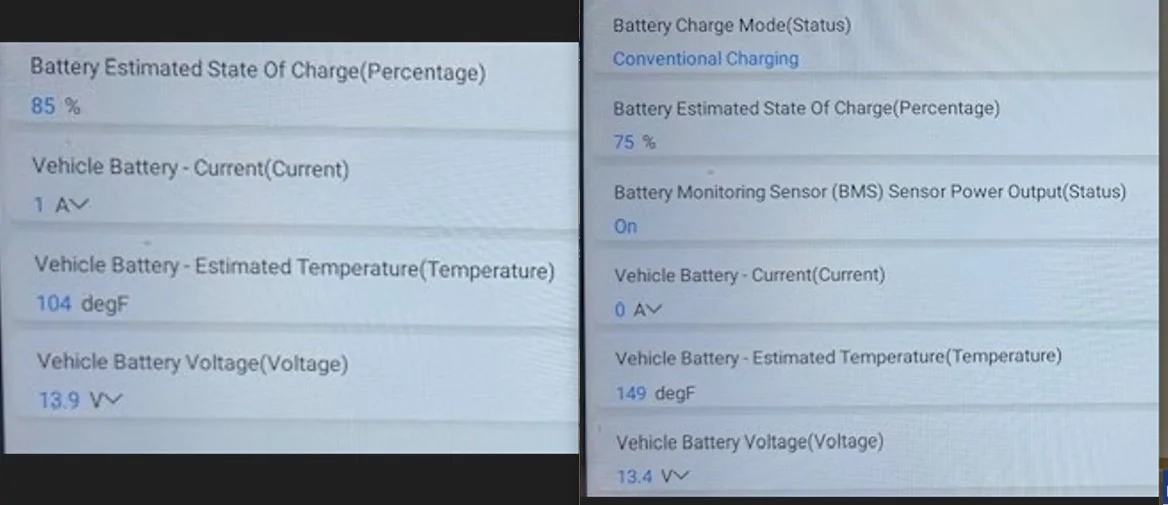
Ref my post (Pic) of the BCM PIDs
The data the BCM sees here is relayed to the PCM to (play a partial role) in factoring the Alternator output and the Desired Setpoint. (Via - Can Bus) communication
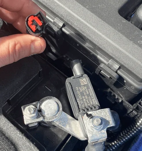
BMS Sensor:
2-Wire but 3 total connections
It's connected to the (Neg) terminal (Grd) - (1)-connection
The Connector: (2-Wire)
one routes to the BCM (LIN) and the other routes over to the (+ Pos) side of the battery BMFL as noted in my pic.
Keep in mind that the Alternator (B+) is also connected to the BMFL, so by chance this BMS sensor is shorted the (Alternator) may be picking it up via the (Bat+) feed
This is why I recommended disconnecting this connector and see what it does.
You need to set up the scan tool to view and monitor 2 separate modules.
The PCM and BCM to see all the relevant PIDs - I posted ALL Available
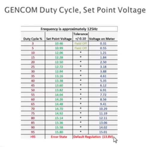
You should also be able to (Bi-Direction) control the Desired Voltage by adjusting the Duty Cycle (PCM)
This is depending on the (Level of the Scan Tool) you have.

I will come back to you at the weekend mate with information we have had the first snow of the winter im gunna throw it in a mates garage at the weekend, i use forscan with genuine vcm2, i have frds but having issues with the licenceCorrect - The Alternator has 2 connections:
B+ and a single wire (LIN) control - this is a data bus wire and its PWM variable voltage.
This is also 2 way communication.
The LIN here is between the PCM & Alternator
The PCM itself is the master for controlling the Alternator / Regulator Output using various inputs the PCM is receiving from other sensors and modules.
(This is where the manuals lack - DETAILED information)
What are the exact factors that determine the output.
One of the factors is the BMS (Battery Mgmt System) which incorporates a sensor on the (-Neg) battery post.
This system also works via LIN between the BMS sensor and the BCM
Ref my post (Pic) of the BCM PIDs
The data the BCM sees here is relayed to the PCM to (play a partial role) in factoring the Alternator output and the Desired Setpoint. (Via - Can Bus) communication
BMS Sensor:
2-Wire but 3 total connections
It's connected to the (Neg) terminal (Grd) - (1)-connection
The Connector: (2-Wire)
one routes to the BCM (LIN) and the other routes over to the (+ Pos) side of the battery BMFL as noted in my pic.
Keep in mind that the Alternator (B+) is also connected to the BMFL, so by chance this BMS sensor is shorted the (Alternator) may be picking it up via the (Bat+) feed
This is why I recommended disconnecting this connector and see what it does.
You need to set up the scan tool to view and monitor 2 separate modules.
The PCM and BCM to see all the relevant PIDs - I posted ALL Available
You should also be able to (Bi-Direction) control the Desired Voltage by adjusting the Duty Cycle (PCM)
This is depending on the (Level of the Scan Tool) you have.
This is where you are faulting - this screenshot is at idle, if I rev the engine (duplicating) yoursI use forscan with
I will come back to you at the weekend mate with information we have had the first snow of the winter im gunna throw it in a mates garage at the weekend, i use forscan with genuine vcm2, i have frds but having issues with the licence
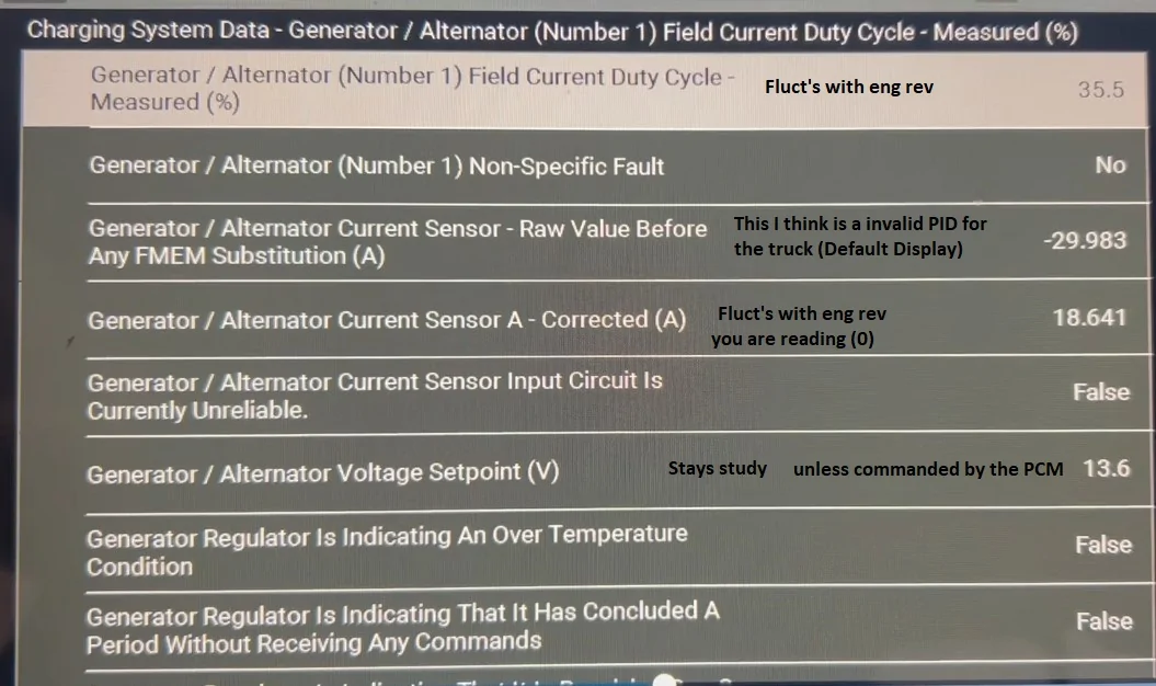
This is where you are faulting - this screenshot is at idle, if I rev the engine (duplicating) yours
the Duty Cycle & Current Sensor rapidly increase (quick snaps)
The PCM is not picking up (receiving) that the alternator is producing output current which is feedback (ref) on the LIN.
You can see the PCM side of the circuit is working as its setting a desired setpoint, so either the alternator is bad, or the LIN circuit is bad, most likely a bad connection (heat) increases the resistance on the circuit, and a bad connection is disabling the output.


I can't see the alternator causing the engine to cut out. I can see the PCM having a problem causing the engine cut out and the alternator voltage to dip at the same time, since it controls both.This is where you are faulting - this screenshot is at idle, if I rev the engine (duplicating) yours
the Duty Cycle & Current Sensor rapidly increase (quick snaps)
The PCM is not picking up (receiving) that the alternator is producing output current which is feedback (ref) on the LIN.
You can see the PCM side of the circuit is working as its setting a desired setpoint, so either the alternator is bad, or the LIN circuit is bad, most likely a bad connection (heat) increases the resistance on the circuit, and a bad connection is disabling the output.
I had a 90's something Oldsmobile that the alternator crapped out in. I looked at local prices and decided my buddy in Southern Maryland could rebuild it for far cheaper. So I grabbed an extra battery connected in parallel to the one under the hood, jumper cables running from passenger floor to the engine compartment, and took off for the 5ish hour drive. Made it with juice to spare. Stayed the night at buddy's house and drove back the next day with my newly rebuilt alternator.I know that I drove 125 miles to my destination on Christmas Eve when the alternator in my 2005 Ranger failed halfway into the trip. Few stores open, and the only parts store that had a replacement alternator in stock was at my destination. I don't think I could have made another 5 miles further down the road either! My Optima yellow top never fully recovered from that deep discharge.
But that was the old Ranger with the regulator built into the alternator, the charging system was largely independent of the ECU, not like the digitally controlled overly complicated charging system found in the 5G Rangers. The more complicated the plumbing the easier it is to stop it up!
These knew systems are so intertwined that systems failures show themselves in other (what would normally be) distinct and separate systems.
Example - A DPFE EGR sensor failure creates serious transmission shift issues. I no longer doubt the wildest of ramifications from any system malfunction in modern autos.
So i disconnected the lin wire and other than a warning light on the dash it ran fine, and the generator desired voltage didnt change and under load still cut.I can't see the alternator causing the engine to cut out. I can see the PCM having a problem causing the engine cut out and the alternator voltage to dip at the same time, since it controls both.
As I said earlier, you can (as a test) unplug the LIN connector on the alternator and run the engine to eliminate it as a possible problem.
That would be the LIN wiring. That communicates the PCM generator voltage setpoint to the generator.So i disconnected the lin wire and other than a warning light on the dash it ran fine, and the generator desired voltage didnt change and under load still cut.
I have the engine loom out at the moment looking at all the wiring as i need to find this "generator desired voltage" line but im suspecting its can related.
I have a full wiring diagram
Although you are correct to possibly address the voltage to the PCM as this still may be the issue or something causing a voltage spike (short) as the throttle is increased.That would be the LIN wiring. That communicates the PCM generator voltage setpoint to the generator.
I am thinking that the generator or its controls is not the cause of your problem, but a symptom of the real problem. I still think you should monitor the power feed to the PCM to see if it is cutting out, causing the engine issue. I can't see a problem with the charging system causing an intermittent engine cut-out.
Ok i have pulled the engine harness and checked it end to end with a load device (bulb) and dont get a fault shown.Although you are correct to possibly address the voltage to the PCM as this still may be the issue or something causing a voltage spike (short) as the throttle is increased.
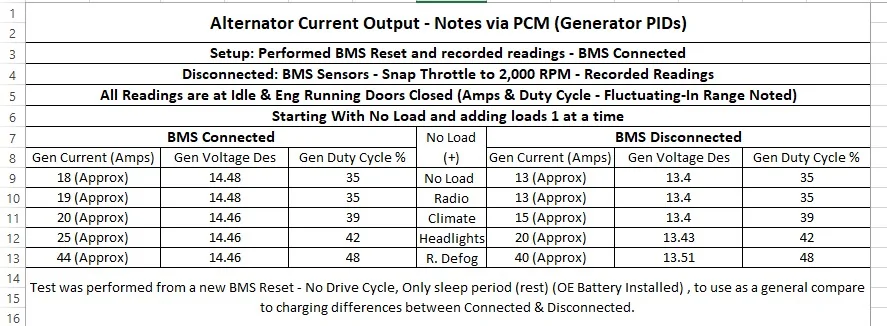
What we need to actually see is (ALL) related PIDs for the charging system to pin it down, we are not seeing that and can only make suggestions at this point.
However, note that a issue on the LIN circuit (voltage rises) as the throttle is increased may be triggering the PCM into LIMP Mode, the same goes for it being disconnected.
So, note: That even with the LIN disconnected there is still power feeding on that wire, if its shorted it will back feed into the PCM - I think this is what we are seeing.
The Ground is being applied via the wire instead of the Regulator and the PCM still thinks the LIN is connected because it is seeing a ground - so it's not going into default charging (Mode) the way it should if you disconnect the LIN wire -it's not seeing an open circuit.
This is why I am FOCUSED on the LIN Circuit.
We are not seeing (ALL) the PIDs for what the Generator does with it disconnected @ Idle and when the RPMs are raised.
So, I agree it's either the PCM (Module Supply) voltage dropping or its the (System Voltage Supply) or the (Inferred Battery Voltage) all of these plus the Desired Set Point Voltage as well as the various other module voltages need to be viewed and the Gen Current and Battery Current.
So, we have a long list of PIDs that we are not being shown, as well as the various PID (fault monitoring) related to the charging system.
It may also be possible that the (LIN) was shorted which again took out the generator (2nd) after it was replaced.
Basically, bottom line is - the PCM appears to have forced LIMP Mode, and this is why the PCM is limiting the RPMs.
Again, a full system scan and or Self-Test Reset of the PCM will / should reveal something as with this test (Automatic) RPM Increase is performed, and it may show something at this point as it will not be able to get a valid response.

 and patience tutorial
 I am working on a hunch - but when you get it back together, I need to know any other issues you are having other than throttle limitation.