OP
OP
airline tech
Well-Known Member
- Joined
- Aug 24, 2022
- Threads
- 28
- Messages
- 4,448
- Reaction score
- 8,499
- Location
- Midwest - KS
- Vehicle(s)
- 2022 Ranger Lariat-Super Crew, Cactus Gray
- Occupation
- Aircraft Tech
- Thread starter
- #91
Quick Checks before a deep dive.
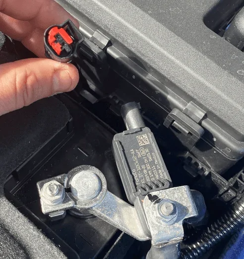
Disconnect the BMS Sensor, I have a hunch it may be shorted and taking out the LIN circuit feed
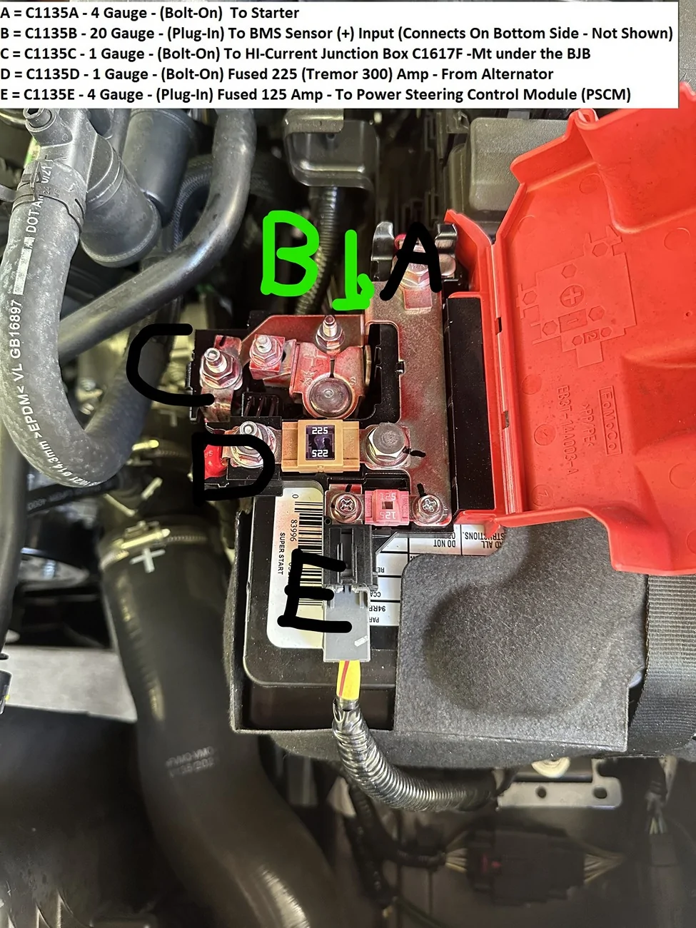
plus, ck and ensure the (Positive) wire from the BMS sensor is connected to the Positive side of the battery.
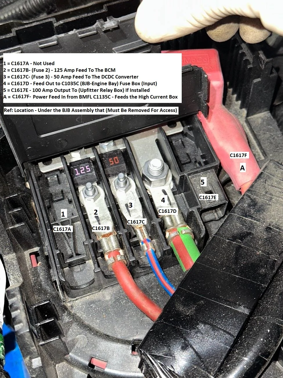
Pull and inspect the 225 Amp Fuse on the BMFL, do not just visually inspect it.
From here its wire checks on the
1. PCM Power Relay Circuit
2. Battery Cable Runs (Pos & Neg)
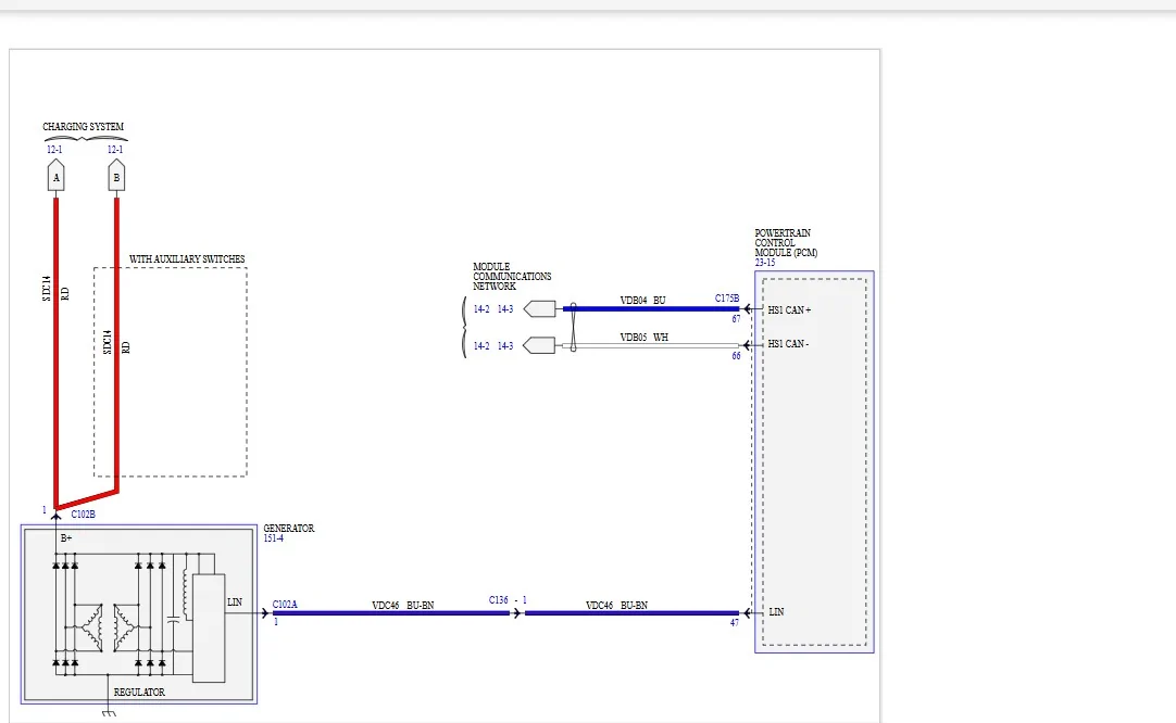
3. LIN Circuit to the Alternator
4. BMS Sensor - Feeds to the BCM
5. CAN Bus Data - Monitor (ISPR) Ignition Switch Position (Run)
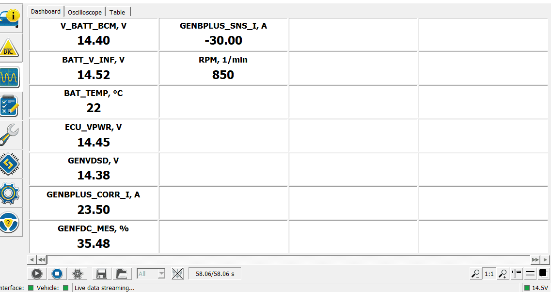
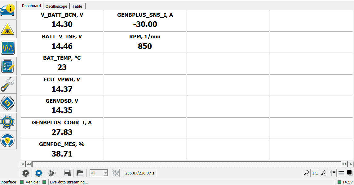
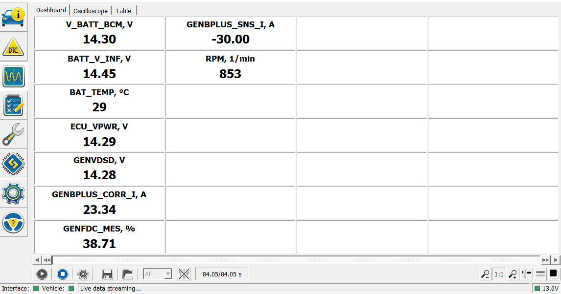
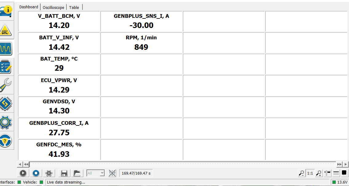
So, between the PCM & BCM and Live Data PIDs, look for any other PIDs that fluctuate
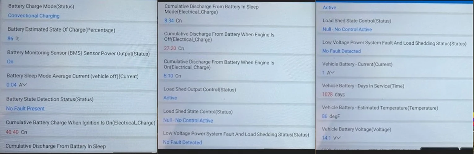
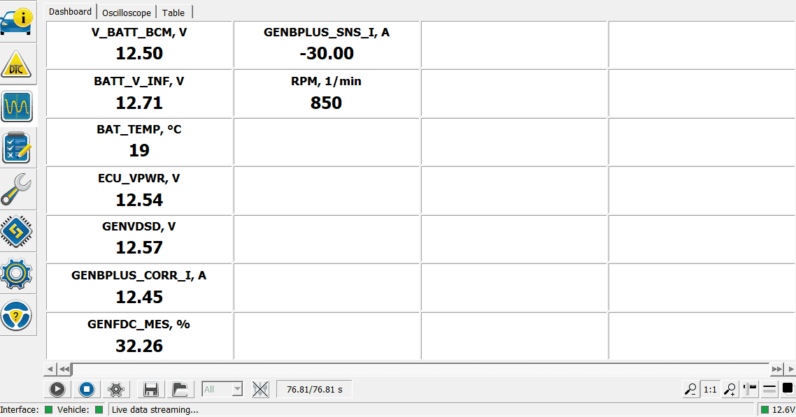
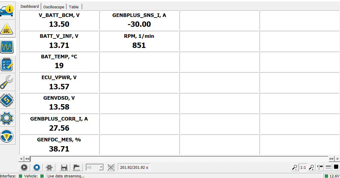
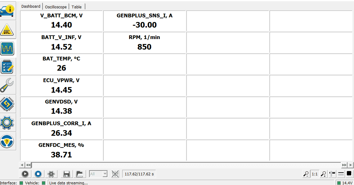
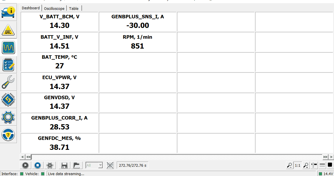
Here are 2 data points of reference from my scan tool for all related PIDs for battery and charging.
All Battery PIDs from the BCM

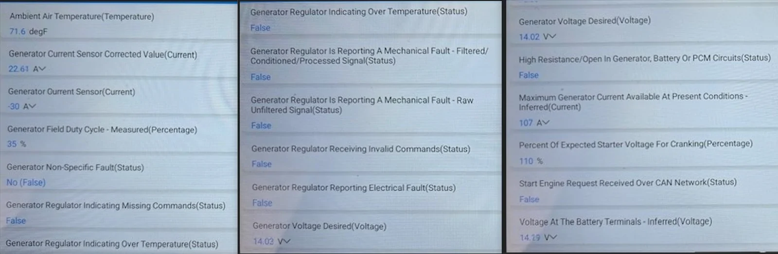
All Charging PIDs from the PCM
Look at - Generator Current Sensor here, then double check yours again - I see (0) on yours

I am going to backtrack on my initial thought for now and focus on the charging system control vs PCM Power Loss or Short.
I am NOT seeing a normal charging voltage (output) from the alternator - Its intermittent)
If there is a fault on the circuit (It defaults to around 13.5 Volts) and the PCM is being under powered and struggling to stay awake other modules pulling power away.
Your throttle issues are (LIMP Mode) activating - voltage loss / under voltage
My hunch is telling me the issue is on the LIN Circuit either to the BCM or PCM.
You may try - Bi-Directional Control of the Gen Voltage Desired - and see if you can control the circuit - I have a hunch (No) and you will not get a valid result of full control.
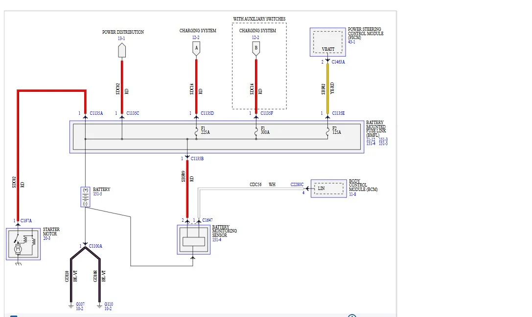
The problem is (posting a US vs) diagram - you have a different engine and most likely different pinouts especially on the PCM as you have a TCM, the US Version the (TCM is merged into the PCM)
I suspect the basic circuit itself is the same - it's just most likely going to pinned differently
The BCM and PCM crosstalk on what the BMS Sensor sees, and it is relayed to the PCM for actual control of the charging output.
So, a deeper dive into the PIDs or Bi-Direction control will reveal what's actually happening

Note: The Inline connector C136 - it should be a (2 - Cavity) Single Wire connector near the battery

Ensure the 225-Amp fuse is good - remove & inspect, this fuse is prone to vibration damage
Ensure the (Pos) wire from the BMS sensor is connected @ B
Ensure integrity & security of (ALL) battery cables
Ensure the Battery is good and not internally shorted cell

Note: This is for a US Version Ranger
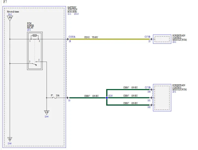
Showing the VPWR feeds to the PCM
Granted I can only offer (this diagram)
Ck Fuse 20 (for corrosion)
Pull and Inspect the PCM Power Relay Contacts (for corrosion)
Pull and inspect the PCM Connector C175B
Pull and Inspect (BJB) Connector C1035A
If needed - Voltage and Resistance Checks on all wiring
If the LIN Circuit checks good, then the issue is here most likely.
But honestly with your video, I am seeing the Gen Desired drop off before the module voltage and its rapidly fluctuating and not holding steady - so this tells me it cannot communicate with the Alternator or the Can Bus Communication between the BCM and PCM is corrupted by a shorted BMS Sensor on that LIN Circuit.

Disconnect the BMS Sensor, I have a hunch it may be shorted and taking out the LIN circuit feed
plus, ck and ensure the (Positive) wire from the BMS sensor is connected to the Positive side of the battery.
Pull and inspect the 225 Amp Fuse on the BMFL, do not just visually inspect it.
From here its wire checks on the
1. PCM Power Relay Circuit
2. Battery Cable Runs (Pos & Neg)
3. LIN Circuit to the Alternator
4. BMS Sensor - Feeds to the BCM
5. CAN Bus Data - Monitor (ISPR) Ignition Switch Position (Run)
So, between the PCM & BCM and Live Data PIDs, look for any other PIDs that fluctuate
Here are 2 data points of reference from my scan tool for all related PIDs for battery and charging.
All Battery PIDs from the BCM
All Charging PIDs from the PCM
Look at - Generator Current Sensor here, then double check yours again - I see (0) on yours
I am going to backtrack on my initial thought for now and focus on the charging system control vs PCM Power Loss or Short.
I am NOT seeing a normal charging voltage (output) from the alternator - Its intermittent)
If there is a fault on the circuit (It defaults to around 13.5 Volts) and the PCM is being under powered and struggling to stay awake other modules pulling power away.
Your throttle issues are (LIMP Mode) activating - voltage loss / under voltage
My hunch is telling me the issue is on the LIN Circuit either to the BCM or PCM.
You may try - Bi-Directional Control of the Gen Voltage Desired - and see if you can control the circuit - I have a hunch (No) and you will not get a valid result of full control.
The problem is (posting a US vs) diagram - you have a different engine and most likely different pinouts especially on the PCM as you have a TCM, the US Version the (TCM is merged into the PCM)
I suspect the basic circuit itself is the same - it's just most likely going to pinned differently
The BCM and PCM crosstalk on what the BMS Sensor sees, and it is relayed to the PCM for actual control of the charging output.
So, a deeper dive into the PIDs or Bi-Direction control will reveal what's actually happening
Note: The Inline connector C136 - it should be a (2 - Cavity) Single Wire connector near the battery
Ensure the 225-Amp fuse is good - remove & inspect, this fuse is prone to vibration damage
Ensure the (Pos) wire from the BMS sensor is connected @ B
Ensure integrity & security of (ALL) battery cables
Ensure the Battery is good and not internally shorted cell
Note: This is for a US Version Ranger
Showing the VPWR feeds to the PCM
Granted I can only offer (this diagram)
Ck Fuse 20 (for corrosion)
Pull and Inspect the PCM Power Relay Contacts (for corrosion)
Pull and inspect the PCM Connector C175B
Pull and Inspect (BJB) Connector C1035A
If needed - Voltage and Resistance Checks on all wiring
If the LIN Circuit checks good, then the issue is here most likely.
But honestly with your video, I am seeing the Gen Desired drop off before the module voltage and its rapidly fluctuating and not holding steady - so this tells me it cannot communicate with the Alternator or the Can Bus Communication between the BCM and PCM is corrupted by a shorted BMS Sensor on that LIN Circuit.
Sponsored
Last edited:

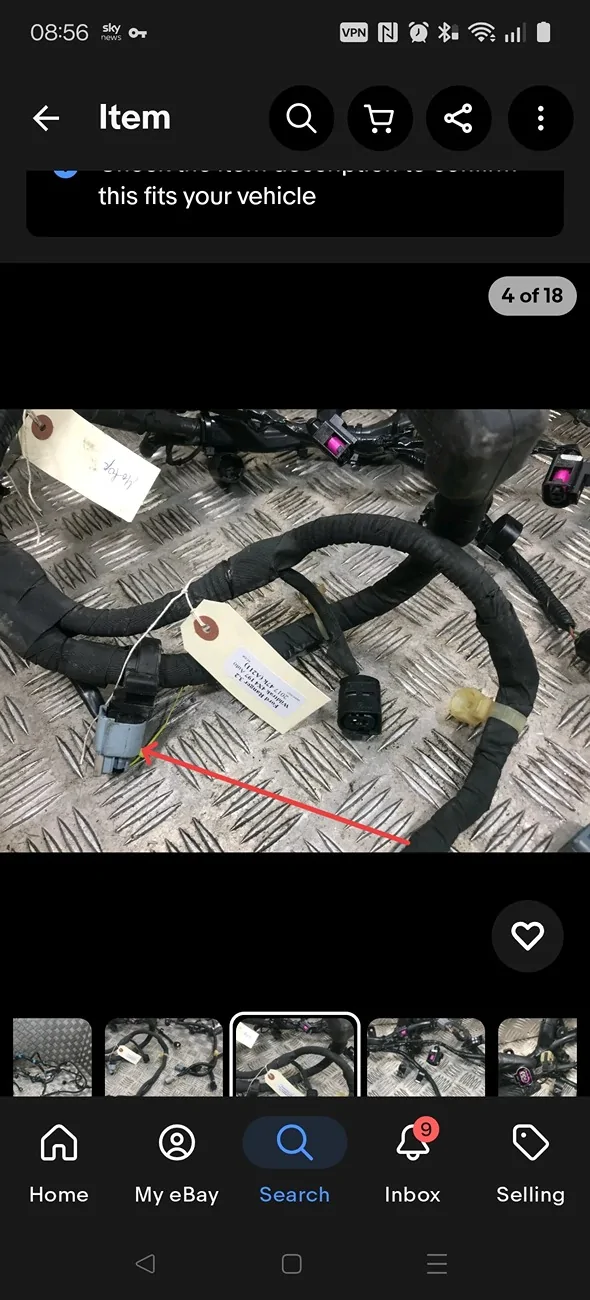
 obviously I've ripped the images off eBay rather than trying to get a pic of it squashed up in the engine bay.