Sponsored

Blower motor quit working

Leecpdk9

New Member
First Name
Lee
Joined
Aug 10, 2023
Threads
1
Messages
4
Reaction score
3
Location
WV
Vehicle(s)
2021 Ford Ranger XLT Super Crew FX4
Occupation
Retired
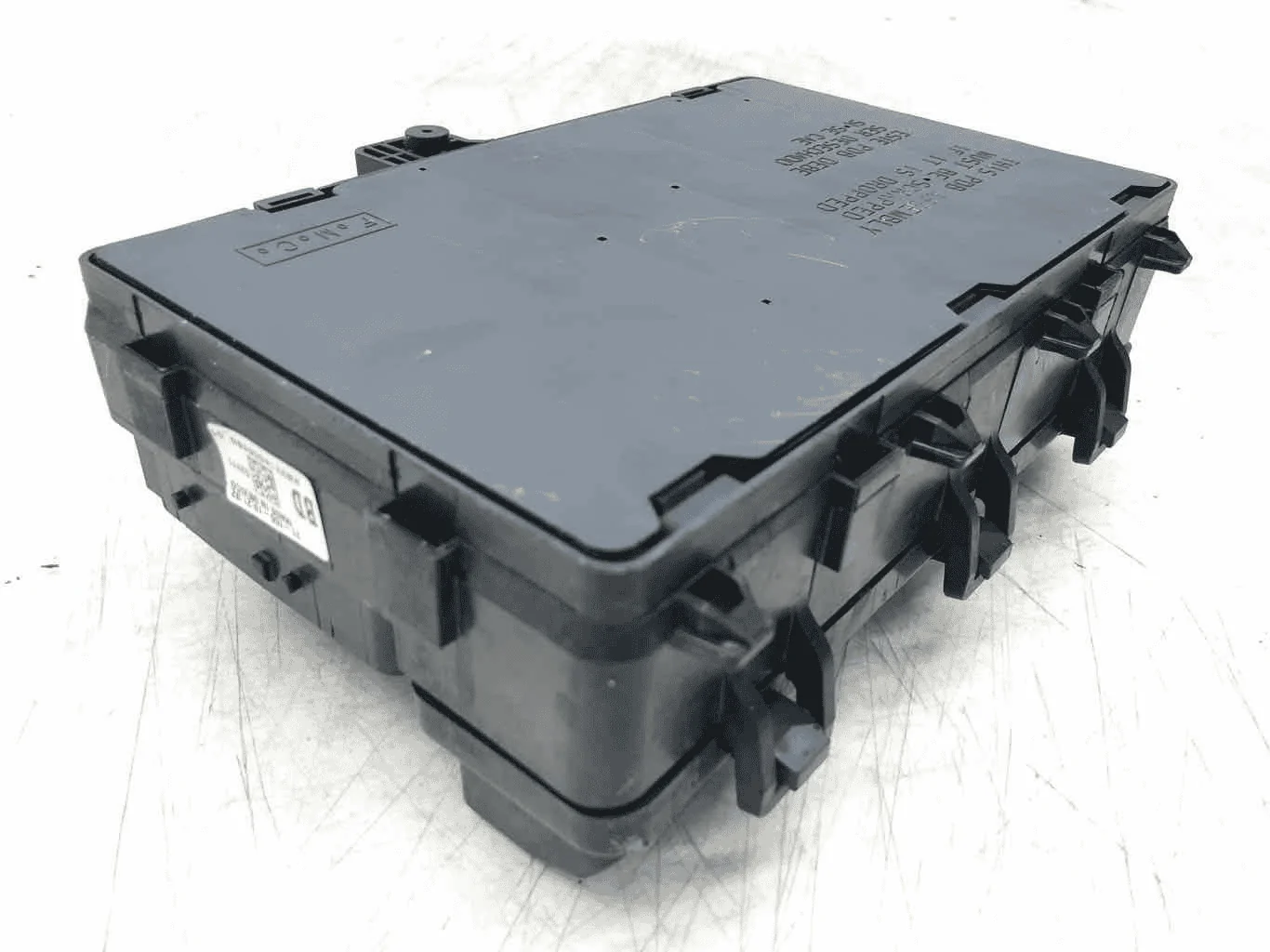
I was looking in the fuse box, I noticed the cover of the starter solenoid relay was busted. I removed the relay, and replaced it back into its slot. My truck wouldn't start. I placed the blower motor relay into the starter relay in case I needed my truck for an emergency until the parts store opened. I placed the busted cover relay into my blower motor relay slot. Now my blower motor doesn't work. No heat. No air. Nothing is blowing.

I get the new relay and place it into the blower motor relay slot and still nothing. So..remembering the original relay for the blower was in my starter solenoid relay slot, I removed that relay and placed it into the blower motor slot and placed the new relay into the starter slot. My truck started but still no blower.

I have checked all relays. They all have continuity. I have checked the fuses under the dash, in the top fuse box and bottom fuse box under the hood and the 4 fuses under the top/bottom box. All are good and all have continuity.

I have searched for a blower motor resistor..and in the 2021 Ranger XLT it is non existent. So that eliminates that part. So I call the dealer and they said this must now be built into the blower motor (although he initially thought there was a resistor). So I purchased a new blower motor. No change.

Blend doors are working.

I checked to see if I am getting 12v to the blower motor. I am not. The compressor is not engaging either.

Any suggestions because Ford won't tell me?
Sponsored


airline tech

Well-Known Member
Joined
Aug 24, 2022
Threads
28
Messages
4,448
Reaction score
8,499
Location
Midwest - KS
Vehicle(s)
2022 Ranger Lariat-Super Crew, Cactus Gray
Occupation
Aircraft Tech
Check fuse 79 (BJB) - 40 Amp fuse first
and
Check Fuse 12 at the BCM (7.5 Amp Fuse)
Then get a scanner or Forscan and pull any B (Body) codes as this should have a code triggered.
That code will help pinpoint troubleshoot.

Try clearing codes as well as the FCIM may have disabled blower until code is reset. I have a strong feeling that this will fix your issue, since the FCIM has shut down and disabled the output voltage to command the Blower Motor -On, the failure was generated when you installed the shorted (Starter Relay)

If you look at attached PDF
To pinpoint if you have a control issue or power feed issue.
Pull out Blower Relay and jumper pins 3 & 5, the blower motor should kick on (high)

Control Side of Relay:
Pin 2 is getting a power feed (signal) from the FCIM and fed to Pin 1 (Ground)
It takes this circuit to command blower motor on
With relay pulled, check for power at Pin 2 with key on and FCIM being set up to have blower motor on.

If I recall the top of the relay should have a pinout diagram on the cover

So, by your post you have no power at Pin 2 of the Blower Control Module - Correct
You should also have power (PWM) Pulse Width Modulated to vary the ground return as this will vary the blower motor speed.
This is the Resistor - In the circuit

If after resetting any codes and problem returns with same code, post the code you are getting to pinpoint the steps to diagnose it plus confirm if you have Dual Automatic Control or Manual

One other note is after clearing Codes, do a self test of the FCIM with the scan tool, this will force a test of the system and when it sees a valid no fault test, full system operation should be available.
 

Attachments

Last edited:
OP
OP

Leecpdk9

New Member
First Name
Lee
Joined
Aug 10, 2023
Threads
1
Messages
4
Reaction score
3
Location
WV
Vehicle(s)
2021 Ford Ranger XLT Super Crew FX4
Occupation
Retired
The system is Duel Auto, The DTC # B10AF:15-0A. Thank you for your help
 

airline tech

Well-Known Member
Joined
Aug 24, 2022
Threads
28
Messages
4,448
Reaction score
8,499
Location
Midwest - KS
Vehicle(s)
2022 Ranger Lariat-Super Crew, Cactus Gray
Occupation
Aircraft Tech
That code ties to the relay coil - open or short to voltage- so if clearing codes and running self test does not fix it - then you will have to dig deeper, if jumping pins 3 and 5 gets it to run then no power is coming from FCIM to signal the blower on.
Note the relay coil is the control side of the relay
I think the FCIM has disabled power as part of the FET protection- it needs to be reset by a Self Test (scan tool)
If you do not have Self Test on tool - try battery disconnect as well
 
Last edited:
OP
OP

Leecpdk9

New Member
First Name
Lee
Joined
Aug 10, 2023
Threads
1
Messages
4
Reaction score
3
Location
WV
Vehicle(s)
2021 Ford Ranger XLT Super Crew FX4
Occupation
Retired
Okay I checked the voltage from the fcim to pin number two on the relay I have 12 volts there also have 12 volts from pin 2 to pin 1 now with those two connected jumped over and I jump three and five I think I see one two yeah three and five the blower ran on high for just a second and then it quit so now I'm at a standstill again any help will be greatly appreciated thank you so much


airline tech

Well-Known Member
Joined
Aug 24, 2022
Threads
28
Messages
4,448
Reaction score
8,499
Location
Midwest - KS
Vehicle(s)
2022 Ranger Lariat-Super Crew, Cactus Gray
Occupation
Aircraft Tech
Here is the pinpoint test for your code, now all this test does is basically test wiring circuit.

So to back up - If you only jumper Pins 3 & 5 at the relay - Then the blower should run, the only influence in the circuit at this point will be the PWM input at the Blower Cont. Module, as this will be the motor speed (varying) the ground return, but I do not think that will come into play unless it sees the completed circuit between Pins 2 and 1 at the relay.
Key position should not matter for this test as Fuse 79 is (Hot at all times)

So, you have confirmed that the motor will run by your test already we at least know the motor is good.

For a brief understanding on how the relay works, power is applied to Pin 2 from the FCIM.
Power flowing through the (Coil) in that circuit creates a magnetic field that pulls the contact down, to complete the circuit between Pins 3 and 5

It appears that the FCIM is dropping power off of Pin 2, to protect the circuit.
So, if you have jumped Pins 2 and 1 and then jumped Pins 3 and 5 and it worked for a second and quit. It may be shutting down due to input from the temperature sensors.

I strongly believe that the FCIM needs to be reset, now the manual does not give you direction on this but the FCIM is protected by a (FET) Field Effect Transistor, this is a internal protection of the FCIM, (It is basically an internal circuit breaker) (Electronic)

This is the most important step as the FCIM needs to be reset.
If you have a Scanner or Forscan, there is a Module Reset or Self-Test that can be ran, this should clear any codes and also reset the (FET)

If fault returns after the reset, then you will have to do the wiring checks noted below, this will show any bad wiring (shorted)

If you do not have this capability, then you can try:
Battery Disconnect - 10 Minutes or so
or
Pulling these fuses:
BJB- Fuse 65 and Fuse 80 and Fuse 79
BCM - Fuse 12
Leave fuses out for 10 Minutes or so.
These Fuses are feeding the FCIM and Blower

So, possibles
Bad FCIM (Internal circuit fried)
Bad MS Can circuit) within the FCIM or Input/Output to it
Bad wiring (Insulation / wire strands) and shorting out the circuit, and the FCIM reacting by killing power
Damaged or Pushed Pin at the Relay connection point on the BJB


NOTE: For the below test, this test indicates that the Blower Motor Relay is internal to the BJB and non servicable, but you clearly have a servicable relay

PINPOINT TEST M : THE BLOWER MOTOR IS INOPERATIVE

Refer to Wiring Diagrams Cell 55 for schematic and connector information.
Normal Operation and Fault Conditions
Air Handling, REFER to: Climate Control System - Vehicles With: Dual Automatic Temperature Control (DATC) - System Operation and Component Description (412-00 Climate Control System - General Information, Description and Operation) .
DTC Fault Trigger Conditions
DTCDescriptionFault Trigger Condition
FCIM B10AF:11Blower Fan Relay: Circuit Short To GroundModule senses low voltage on the relay coil voltage circuit when the module is energizing the circuit. Blower relay is permanently inactive.
FCIM B10AF:15Blower Fan Relay: Circuit Short To Battery Or OpenModule senses greater than expected voltage on the blower relay coil voltage circuit, indicating an open circuit or a short to voltage. The blower motor relay is inactive when circuit is open; the blower motor relay is on all the time when shorted to battery.
FCIM B10B9:12Blower Control: Circuit Short To BatteryModule senses high voltage on the blower motor control PWM circuit, indicating a short directly to battery. The blower motor is inoperative.
FCIM B10B9:14Blower Control: Circuit Short To Ground Or OpenModule senses low voltage on the blower motor control PWM circuit, indicating a short directly to ground or an open circuit. The blower motor runs at full speed when circuit is shorted to ground. The blower motor is inoperative when circuit is open.
Possible Sources
  • Fuse
  • Wiring, terminals or connectors
  • Blower motor relay (non-serviceable, part of the BJB )
  • Blower motor
  • Blower motor control module
  • FCIM
Visual Inspection and Pre-checks
  • Make sure BJB fuse 79 (40A) is OK.
NOTICE: Use the correct probe adapter(s) when making measurements. Failure to use the correct probe adapter(s) may cause damage to the connector.
M1 CHECK THE BLOWER MOTOR RELAY CONTROL CIRCUIT FOR A SHORT TO GROUND
  • Ignition OFF.
  • Disconnect BJB C1035A .
  • Disconnect FCIM C2402A .
  • Measure:

    Connectors:
    FRONT CONTROLS INTERFACE MODULE (FCIM)
    image
    Open In New TabZoom/Print​
    Positive LeadMeasurement / ActionNegative Lead
    C2402A-11
    image
    Ground
Is the resistance greater than 10,000 ohms?

Yes
GO to M2
No
REPAIR the circuit.​
M2 CHECK THE BLOWER MOTOR RELAY COIL CONTROL CIRCUIT FOR AN OPEN
NOTE: Some vehicles may be equipped with a diode in the blower motor relay coil ground circuit. Make sure the multimeter leads are correctly attached during testing or a false reading will occur causing misdiagnosis of the circuit. For additional information, refer to the Wiring Diagrams manual.
  • Measure:

    Connectors:
    FRONT CONTROLS INTERFACE MODULE (FCIM)
    BATTERY JUNCTION BOX (BJB)
    Open In New TabZoom/Print​
    Positive LeadMeasurement / ActionNegative Lead
    C2402A-11
    image
    C1035A-26
Is the resistance less than 3 ohms?

Yes
GO to M3
No
REPAIR the circuit.​
M3 CHECK THE BLOWER MOTOR CONTROL MODULE CIRCUITS FOR A SHORT TO VOLTAGE
  • Disconnect Blower motor control module C297 .
  • Ignition ON.
  • Measure:

    Connectors:
    BLOWER MOTOR CONTROL MODULE
    image
    Open In New TabZoom/Print​
    Positive LeadMeasurement / ActionNegative Lead
    C297-2
    image
    Ground
    C297-3
    image
    Ground
Is any voltage present?

Yes
REPAIR the affected circuit.​
No
GO to M4
M4 CHECK THE BLOWER MOTOR CONTROL MODULE POWER CIRCUIT FOR A SHORT TO GROUND
  • Ignition OFF.
  • Measure:

    Connectors:
    BLOWER MOTOR CONTROL MODULE
    image
    Open In New TabZoom/Print​
    Positive LeadMeasurement / ActionNegative Lead
    C297-2
    image
    Ground
Are the resistances greater than 10,000 ohms?

Yes
GO to M5
No
REPAIR the circuit.​
M5 CHECK THE BLOWER MOTOR CONTROL MODULE CIRCUITS FOR AN OPEN
  • Measure:

    Connectors:
    BLOWER MOTOR CONTROL MODULE
    BATTERY JUNCTION BOX (BJB)
    Open In New TabZoom/Print​
    Positive LeadMeasurement / ActionNegative Lead
    C297-2
    image
    C1035A-3


    Connectors:
    BLOWER MOTOR CONTROL MODULE
    FRONT CONTROLS INTERFACE MODULE (FCIM)
    Open In New TabZoom/Print​
    Positive LeadMeasurement / ActionNegative Lead
    C297-3
    image
    C2402A-23


    Connectors:
    BLOWER MOTOR CONTROL MODULE
    image
    Open In New TabZoom/Print​
    Positive LeadMeasurement / ActionNegative Lead
    C297-4
    image
    Ground
Are the resistances less than 3 ohms?

Yes
GO to M6
No
REPAIR the affected circuit.​
M6 CHECK FOR CORRECT BLOWER MOTOR CONTROL MODULE OPERATION
  • Ignition OFF.
  • Disconnect and inspect the blower motor control module connectors.
  • Repair:
    • corrosion (install new connector or terminals – clean module pins)
    • damaged or bent pins – install new terminals/pins
    • pushed-out pins – install new pins as necessary
  • Reconnect the blower motor control module connector and all other disconnected connectors. Make sure they seat and latch correctly.
  • Operate the system and determine if the concern is still present.
Is the concern still present?

Yes
INSTALL a new blower motor control module. REFER to the appropriate procedure in Group 412. TEST the system for normal operation. If the concern is still present, GO to M7
No
The system is operating correctly at this time. The concern may have been caused by a loose or corroded connector. ADDRESS the root cause of any connector or pin issues.​
M7 CHECK FOR CORRECT FCIM (FRONT CONTROLS INTERFACE MODULE) OPERATION
  • Ignition OFF.
  • Disconnect and inspect all FCIM electrical connectors (if not previously disconnected).
  • Repair:
    • corrosion (install new connector or terminal - clean module pins)
    • damaged or bent pins - install new terminals or pins
    • pushed-out pins - install new pins as necessary
  • Connect all FCIM electrical connectors. Make sure they seat and latch correctly.
  • Operate the system and determine if the concern is still present.
Is the concern still present?

Yes
CHECK OASIS for any applicable service articles: TSB , GSB , SSM or FSA . If a service article exists for this concern, DISCONTINUE this test and FOLLOW the service article instructions. If no service articles address this concern, Click here to access Guided Routine (FCIM). .​
No
The system is operating correctly at this time. The concern may have been caused by a loose or corroded connector. ADDRESS the root cause of any connector or pin issues.​


Below is the FET protection that I think is triggered.

FCIM - Dual Automatic Temperature Control (DATC)

The DATC system uses the FCIM as the HVAC control module. The FCIM also controls the outputs for rear window defrost and climate controlled seats. For details on the FCIM communication, refer to Control System Logic in this section.

The FCIM utilizes a Field-Effect Transistor (FET) protective circuit strategy for its actuator outputs. Output load (current level) is monitored for excessive current (typically short circuits) and is shut down (turns off the voltage or ground provided by the module) when a fault event is detected. A short circuit DTC is stored at the fault event and a cumulative counter is started.

When the demand for the output is no longer present, the module resets the Field-Effect Transistor (FET) circuit protection to allow the circuit to function. The next time the driver requests a circuit to activate that has been shut down by a previous short (Field-Effect Transistor (FET) protection) and the circuit is still shorted, the Field-Effect Transistor (FET) protection shuts off the circuit again and the cumulative counter advances.

When the excessive circuit load occurs often enough, the module shuts down the output until a repair procedure is carried out. The Field-Effect Transistor (FET) protected circuit has 3 predefined levels of short circuit tolerance based on the harmful effect of each circuit fault on the Field-Effect Transistor (FET) and the ability of the Field-Effect Transistor (FET) to withstand it. A module lifetime level of fault events is established based upon the durability of the Field-Effect Transistor (FET). If the total tolerance level is determined to be 600 fault events, the 3 predefined levels would be 200, 400 and 600 fault events.

When each tolerance level is reached, the short circuit DTC that was stored on the first failure cannot be cleared by a command to clear the Diagnostic Trouble Codes (DTCs). The module does not allow the DTC to be cleared or the circuit to be restored to normal operation until a successful self-test proves that the fault has been repaired. After the self-test has successfully completed (no on-demand Diagnostic Trouble Codes (DTCs) present), DTC U1000:00 and the associated DTC (the DTC related to the shorted circuit) automatically clears and the circuit function returns.

When each level is reached, the DTC associated with the short circuit sets along with DTC U1000:00. These Diagnostic Trouble Codes (DTCs) can be cleared using the diagnostic scan tool. The module never resets the fault event counter to zero and continues to advance the fault event counter as short circuit fault events occur.

If the number of short circuit fault events reach the third level, then Diagnostic Trouble Codes (DTCs) U1000:00 and U3000:49 set along with the associated short circuit DTC . DTC U3000:49 cannot be cleared and a new module must be installed after the repair.

The FCIM requires PMI when it is replaced.


airline tech

Well-Known Member
Joined
Aug 24, 2022
Threads
28
Messages
4,448
Reaction score
8,499
Location
Midwest - KS
Vehicle(s)
2022 Ranger Lariat-Super Crew, Cactus Gray
Occupation
Aircraft Tech
Out of curiosity- have you tried adjusting temp setting to a higher temp for heat.
Do you get the blower motor speed selection on the Sync screen and if so what happens if you select it up or down.
Also try with manual buttons- instead of touchscreen.
Have you tried selecting manual control vs auto?
 

airline tech

Well-Known Member
Joined
Aug 24, 2022
Threads
28
Messages
4,448
Reaction score
8,499
Location
Midwest - KS
Vehicle(s)
2022 Ranger Lariat-Super Crew, Cactus Gray
Occupation
Aircraft Tech
I don’t know why - copy / paste dumps part of the paste. I will post a PDF of the pinpoint test.
 

airline tech

Well-Known Member
Joined
Aug 24, 2022
Threads
28
Messages
4,448
Reaction score
8,499
Location
Midwest - KS
Vehicle(s)
2022 Ranger Lariat-Super Crew, Cactus Gray
Occupation
Aircraft Tech
Its showing on computer, but not on phone, phone drops all of the pics.
Hopefully, you can get it going with what I have posted.
The most likely problem is the FCIM, either needs reset or you have a shorted (burned) wiring in the circuit that is keeping it from running.
If it senses a voltage a voltage anomaly it will shut down the system to protect the FCIM itself
You should be under warranty as the FCIM is about $1,000 for part, if that is fried.
 
OP
OP

Leecpdk9

New Member
First Name
Lee
Joined
Aug 10, 2023
Threads
1
Messages
4
Reaction score
3
Location
WV
Vehicle(s)
2021 Ford Ranger XLT Super Crew FX4
Occupation
Retired
Blower Fixed!!! Thank you to all that responded, the problem was a dropped pin in the BJB. I Replced the Box, with all relays and fuses for about 85.00. I will let everyone know what I find inside the bjb, I'm going to open the permanently sealed box and find out what went wrong, it's junk anyway, might as well learn something from it!!!!!
 

airline tech

Well-Known Member
Joined
Aug 24, 2022
Threads
28
Messages
4,448
Reaction score
8,499
Location
Midwest - KS
Vehicle(s)
2022 Ranger Lariat-Super Crew, Cactus Gray
Occupation
Aircraft Tech
The pin end of the wire has a small spring loaded clip that holds it in place , if you have access to the bottom side just push upwards on it to snap it back in place.

But since you are saying it is a sealed unit , I am assuming it is a circuit board, this may explain why the service manual states - part of the BJB when referring to the relay.
Congratulations on the fix, fluke that it happened
 

airline tech

Well-Known Member
Joined
Aug 24, 2022
Threads
28
Messages
4,448
Reaction score
8,499
Location
Midwest - KS
Vehicle(s)
2022 Ranger Lariat-Super Crew, Cactus Gray
Occupation
Aircraft Tech
Using an Ebay Pic, does yours have a bottom cover like this?

If it has another plastic box attached, they will separate allowing access to this cover.
Now inside this, you will find wiring or a PCB? at the relay and fuse connections.
Normally its wired but the Ranger IDK.


1692411573407.png
 

Racket

Well-Known Member
First Name
John
Joined
Jan 21, 2020
Threads
22
Messages
2,203
Reaction score
3,402
Location
Here and There
Vehicle(s)
2019 Lariat Supercrew 2WD
Occupation
Transient
The pin end of the wire has a small spring loaded clip that holds it in place , if you have access to the bottom side just push upwards on it to snap it back in place.

But since you are saying it is a sealed unit , I am assuming it is a circuit board, this may explain why the service manual states - part of the BJB when referring to the relay.
Congratulations on the fix, fluke that it happened
I've been on a few auto forums and while some devolve into preschool playgrounds others benefit from overt corporate and aftermarket vendor marketing channels. There is an F-150 forum with an official Ford account respondent. Only one other significant Ranger-centric one and it's easy to get lost there - I think I've spotted some of our members there, but this one is superior.

@airline tech is a standout member in my mind, someone who adds enormous value to participating and while there are other notables I'd like to thank him/you for being here and contributing!

??
 

airline tech

Well-Known Member
Joined
Aug 24, 2022
Threads
28
Messages
4,448
Reaction score
8,499
Location
Midwest - KS
Vehicle(s)
2022 Ranger Lariat-Super Crew, Cactus Gray
Occupation
Aircraft Tech
I've been on a few auto forums and while some devolve into preschool playgrounds others benefit from overt corporate and aftermarket vendor marketing channels. There is an F-150 forum with an official Ford account respondent. Only one other significant Ranger-centric one and it's easy to get lost there - I think I've spotted some of our members there, but this one is superior.

@airline tech is a standout member in my mind, someone who adds enormous value to participating and while there are other notables I'd like to thank him/you for being here and contributing!

??
Thank You, :bow:
I like to help as much as I can, plus I learn the various Ranger systems in the process.
 

Racket

Well-Known Member
First Name
John
Joined
Jan 21, 2020
Threads
22
Messages
2,203
Reaction score
3,402
Location
Here and There
Vehicle(s)
2019 Lariat Supercrew 2WD
Occupation
Transient
I went out to look at this and it isn't obvious how there could be a problem. The fact that it has been makes me think a completely different bracket with two or three mounting points might postpone failure beyond the life of the components.
Sponsored


Top