airline tech
Well-Known Member
- Joined
- Aug 24, 2022
- Threads
- 28
- Messages
- 4,447
- Reaction score
- 8,498
- Location
- Midwest - KS
- Vehicle(s)
- 2022 Ranger Lariat-Super Crew, Cactus Gray
- Occupation
- Aircraft Tech
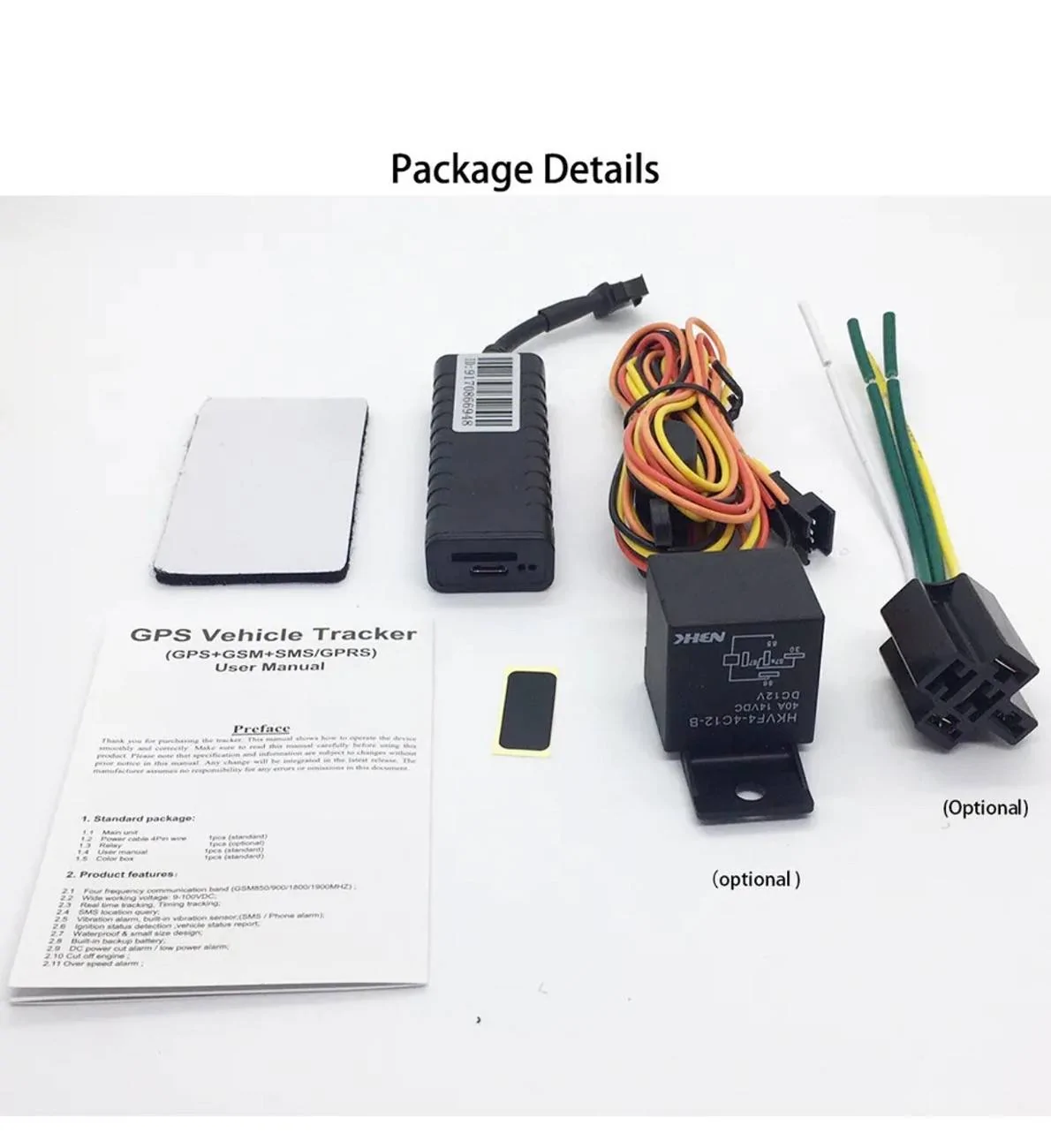
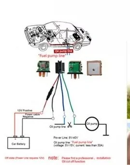
I am assuming you have something like this

If this is the case, then look for something similar, except (Remote-FOB) controlled
As the unit you are looking at - is transferring power - Input to Output
A Relay - Like this is using a 12-Volt - Constant Power Source to Control / Kill the output circuit and is the same function as installing a Toggle/Rocker switch (that you have to manually switch)
Sponsored