Sponsored

(TM) rotary switch-wiring diagram

ControlNode

Well-Known Member
First Name
John
Joined
Nov 29, 2021
Threads
16
Messages
1,710
Reaction score
3,643
Location
Eastern NC
Vehicle(s)
84 Civic "2000S"/16 Focus RS/21 Ranger XLT
Occupation
Computers
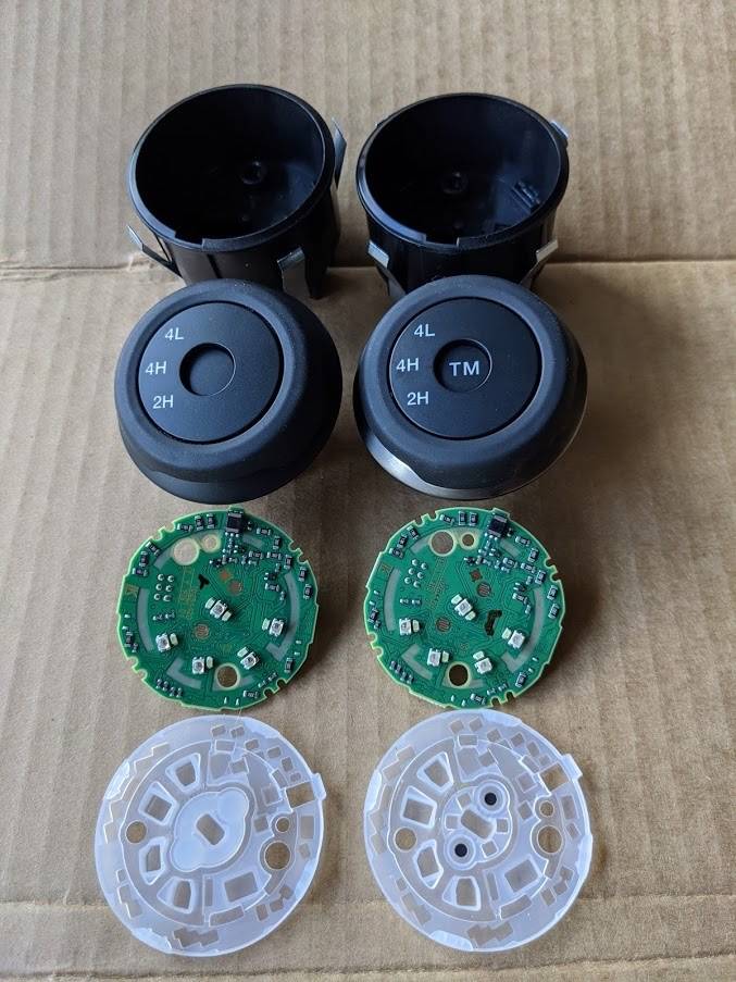
@airline tech Yeah the only data out of the US switch is on the can bus (HS2), I don't even think the US switch internally knows where it is. I think it just signals that the rotary knob was turned left/right (-/+) and if the TM switch was pressed, it listens on the can bus for what it should indicate. So, no real way to direct re-pin the ROW Ranger to support the US switch. As mentioned, it could be done if someone was really wanted to build a module to "rosette stone" the two systems.
Sponsored

 
OP
OP
Pasparakis

Pasparakis

Active Member
First Name
Pasparakis
Joined
Sep 16, 2021
Threads
3
Messages
43
Reaction score
4
Location
Greece
Vehicle(s)
Ranger wildtrak 2.0 biturbo 213ps
Occupation
6 months
As I posted in one of my previous posts, you can get little computer, like a raspberry pi or Arduino, and use a can bus shield attachment for it. But you'll still need to design all the circuits to replicate your switch to the truck's original expectation and the controlling logic to receive and send the proper can bus signals from the rotary switch and potentially other systems of the truck especially if you're trying to use the integrated TM switch.
I understand what you're saying, but I don't have the knowledge to build something like this…we will be able to build if someone guided me..
can you guide me?
 
OP
OP
Pasparakis

Pasparakis

Active Member
First Name
Pasparakis
Joined
Sep 16, 2021
Threads
3
Messages
43
Reaction score
4
Location
Greece
Vehicle(s)
Ranger wildtrak 2.0 biturbo 213ps
Occupation
6 months
I have looked at this as well, and I believe as far as the switch goes, it MAY work, as all the switch is doing is providing contact points in the switch to command the relays to power.
However, I believe the TM button will not be active., since the US version is Data Bus, the Non-Us wiring will not register it being pressed.
The other issue will be getting it into 4-LOW, it possibly may not switch into it.

It highly depends on how the internals of the US versions of the switch is made, I am thinking that it should be a normal switch (contact points), and all that differs is how the switch position is communicated. (CAN vs Direct Wire)
One other issue can the switch handle 12v's on the CAN Bus Terminals and will it provide enough voltage to the relays to make them power.
FYI: We cannot see the internal diagram of the switch (US Version), only pinouts.

If you have already ordered the switch, it may be at least worth a try.
How does your version of the Ranger switch into TM, is it a separate switch?

Edit:
I just remembered something, the US version switch, will rotate 360 degrees, so this may create an issue, the 3 positions are picked up from the data bus.

Edit #2:

Well crap, I looked at the Euro, diagram again and noted / saw the signal return, so this is most likely a 5-Volt Reference (?) circuit to the PCM, then the PCM sends the info along to the relays which are going to be 12-volt relays. I was looking at both Euro and US. :facepalm: and had a rotary switch in my head. (Signal return = Switch Position via the voltage measured on the return circuit) the voltage will vary depending on switch position from the voltage drop across each resistor (switch position)

? = Reference circuits can vary in voltage, and I cannot see what Euro uses, the only way to tell for sure is to measure the input voltage without actually seeing the full wiring manual for this truck.
It could be 5, 9 or 12 volts. But I thinking it is a 5-Volt circuit.

Now, the US version switch should be similar, however with the switch being able to rotate 360 degrees I don't know if the PCM would actually pick up the switch position without an external control device like ControlNode has posted.
The US version should have a resistor set like the Euro version, but the resistor voltage drop will most likely be different and the PCM won't be able to read switch position.
Thank you for your answer…
I haven't ordered a switch yet..want to make sure I don't waste money..
How does your version of the Ranger switch into TM, is it a separate switch? : the only ranger in europe europe is raptor with same switch but it has a (mode button) on the steering wheel..
I measured voltage and it is 5 volts..
I really don't think there is a way to do all of this and it makes me sad…
 
OP
OP
Pasparakis

Pasparakis

Active Member
First Name
Pasparakis
Joined
Sep 16, 2021
Threads
3
Messages
43
Reaction score
4
Location
Greece
Vehicle(s)
Ranger wildtrak 2.0 biturbo 213ps
Occupation
6 months
I have looked at this as well, and I believe as far as the switch goes, it MAY work, as all the switch is doing is providing contact points in the switch to command the relays to power.
However, I believe the TM button will not be active., since the US version is Data Bus, the Non-Us wiring will not register it being pressed.
The other issue will be getting it into 4-LOW, it possibly may not switch into it.

It highly depends on how the internals of the US versions of the switch is made, I am thinking that it should be a normal switch (contact points), and all that differs is how the switch position is communicated. (CAN vs Direct Wire)
One other issue can the switch handle 12v's on the CAN Bus Terminals and will it provide enough voltage to the relays to make them power.
FYI: We cannot see the internal diagram of the switch (US Version), only pinouts.

If you have already ordered the switch, it may be at least worth a try.
How does your version of the Ranger switch into TM, is it a separate switch?

Edit:
I just remembered something, the US version switch, will rotate 360 degrees, so this may create an issue, the 3 positions are picked up from the data bus.

Edit #2:

Well crap, I looked at the Euro, diagram again and noted / saw the signal return, so this is most likely a 5-Volt Reference (?) circuit to the PCM, then the PCM sends the info along to the relays which are going to be 12-volt relays. I was looking at both Euro and US. :facepalm: and had a rotary switch in my head. (Signal return = Switch Position via the voltage measured on the return circuit) the voltage will vary depending on switch position from the voltage drop across each resistor (switch position)

? = Reference circuits can vary in voltage, and I cannot see what Euro uses, the only way to tell for sure is to measure the input voltage without actually seeing the full wiring manual for this truck.
It could be 5, 9 or 12 volts. But I thinking it is a 5-Volt circuit.

Now, the US version switch should be similar, however with the switch being able to rotate 360 degrees I don't know if the PCM would actually pick up the switch position without an external control device like ControlNode has posted.
The US version should have a resistor set like the Euro version, but the resistor voltage drop will most likely be different and the PCM won't be able to read switch position.
i found this foto from here : https://www.ranger5g.com/forum/threads/terrain-management-upgrade.4901/page-23

IMG_6954.jpeg
Sponsored


Top