WCCperfromance
Member
- Thread starter
- #1
Would anyone be able to help me
I’m trying to identify some wiring
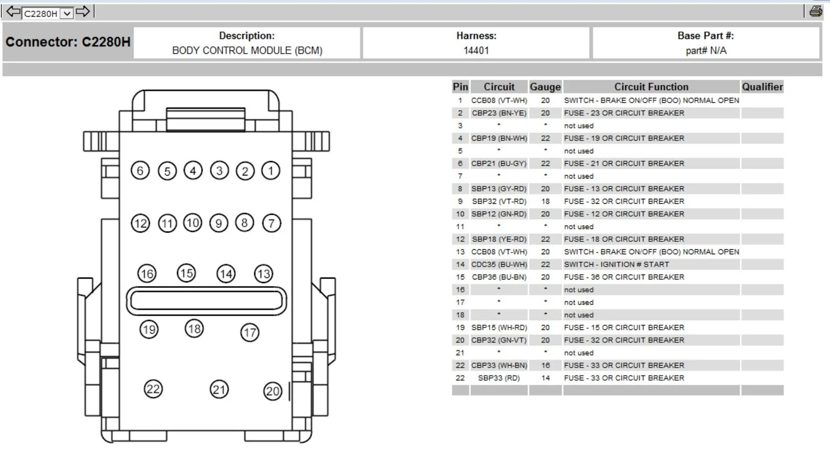
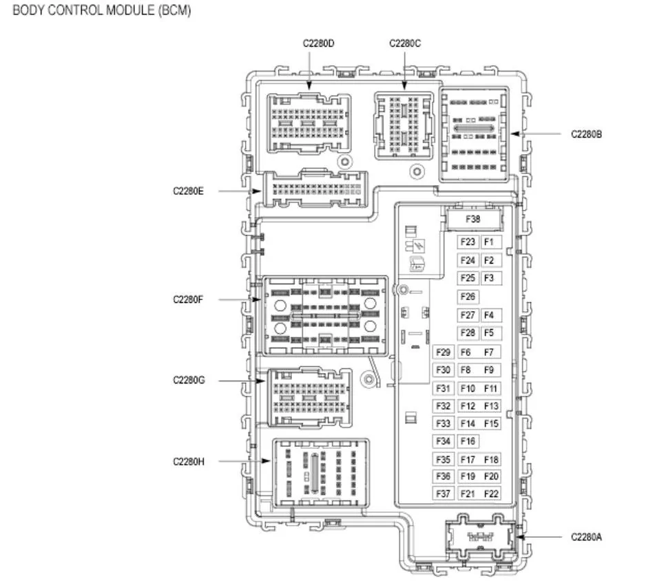
If someone has the wiring diagrams for the bcm fuse box plugs
Ones in the dashboard area
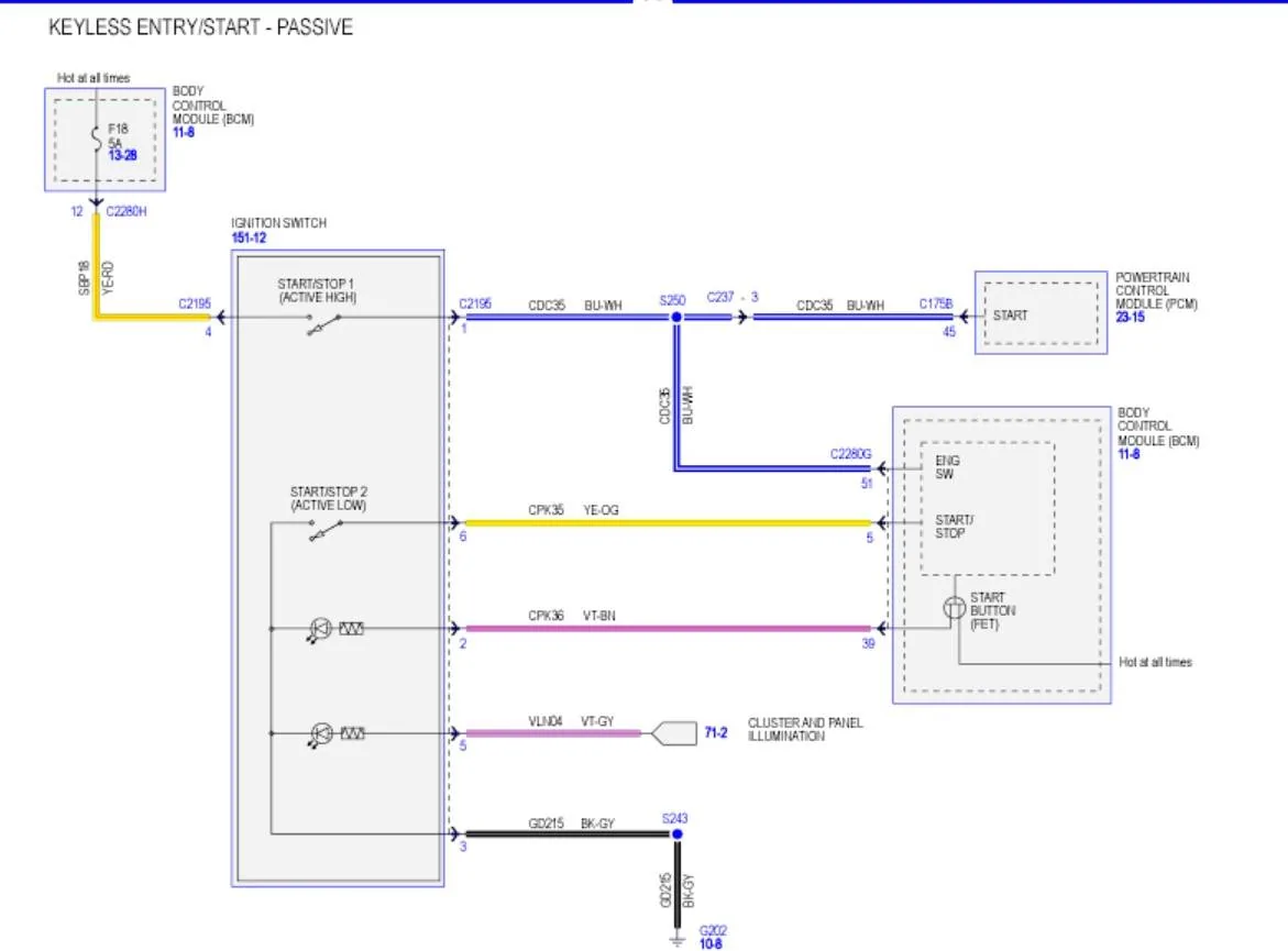
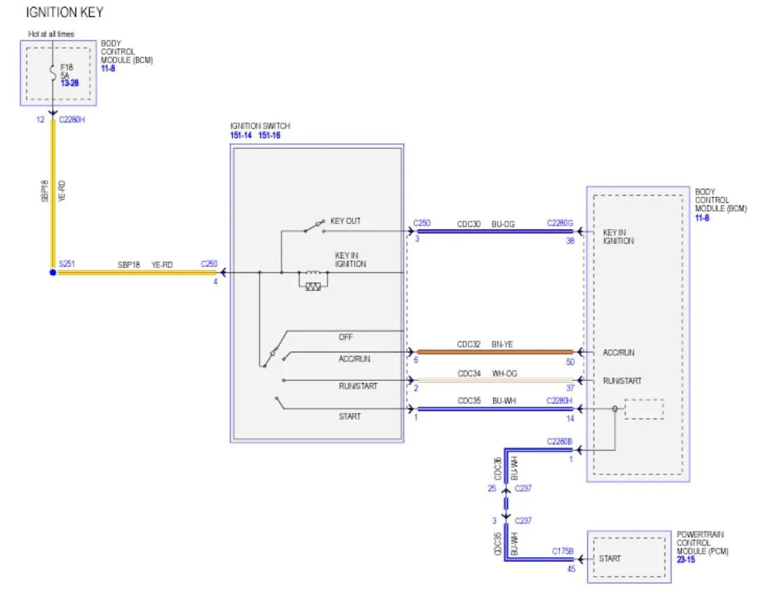
I’m trying to identify the ignition feed wire to fit a kill switch as in the uk the keyless rangers are getting stolen too often
Thanks if anyone can help
I’m trying to identify some wiring
If someone has the wiring diagrams for the bcm fuse box plugs
Ones in the dashboard area
I’m trying to identify the ignition feed wire to fit a kill switch as in the uk the keyless rangers are getting stolen too often
Thanks if anyone can help
Sponsored