Sponsored

@Engineers: Cantilever Deflection Question (Non-Static Load)

OFC Ranger

Well-Known Member
First Name
Jack
Joined
Aug 3, 2020
Threads
297
Messages
5,019
Reaction score
13,926
Location
Georgia
Vehicle(s)
ZR2
In addressing some other after-thoughts on my over the cab rack build and I think I will finally address the ability to free-float the system instead of having to continue to use two hidden "feet" to prevent front end bounce.

I'm still researching as best I can an answer to my question, but I know some of you on here do this for a living and can either provide some insight, or point me in a better direction than blindly searching out on Google regarding cantilever mechanics. I'll get to that question in a moment after some context;

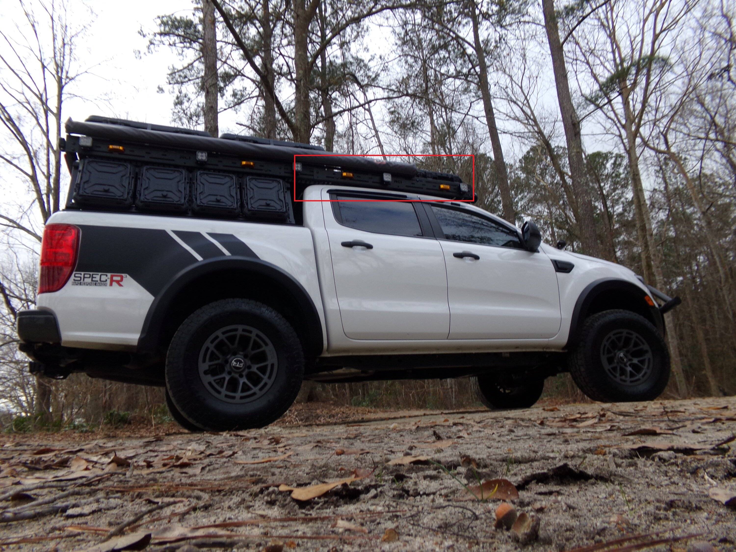
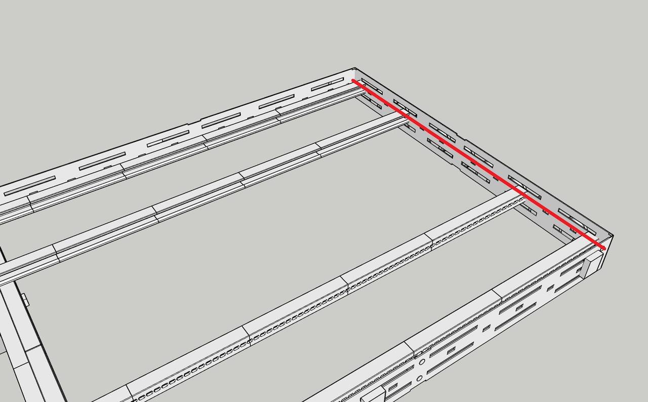
On the new rack variation I will be installing a sub frame piece on the very front (behind the paneling), think of my rack as a box, with an open top in your mind. The open top is the front of the rack. Currently the front is braced by means of the front panel having two L bracket connections on the back side, then the front panel connecting to the side panels which results in two addition fixed contact points on the corners.

The two middle red markers are the L brackets secured by grade 8 bolts, the corners are bend on bend hard contact points, also secured by grade 8 bolts.

rack-1.jpg


The new setup will have a new sub frame piece running corner to corner across the entire span of the front and THAT is what the front panel will connect to, instead of just the corners and two L brackets.

rack-2.jpg


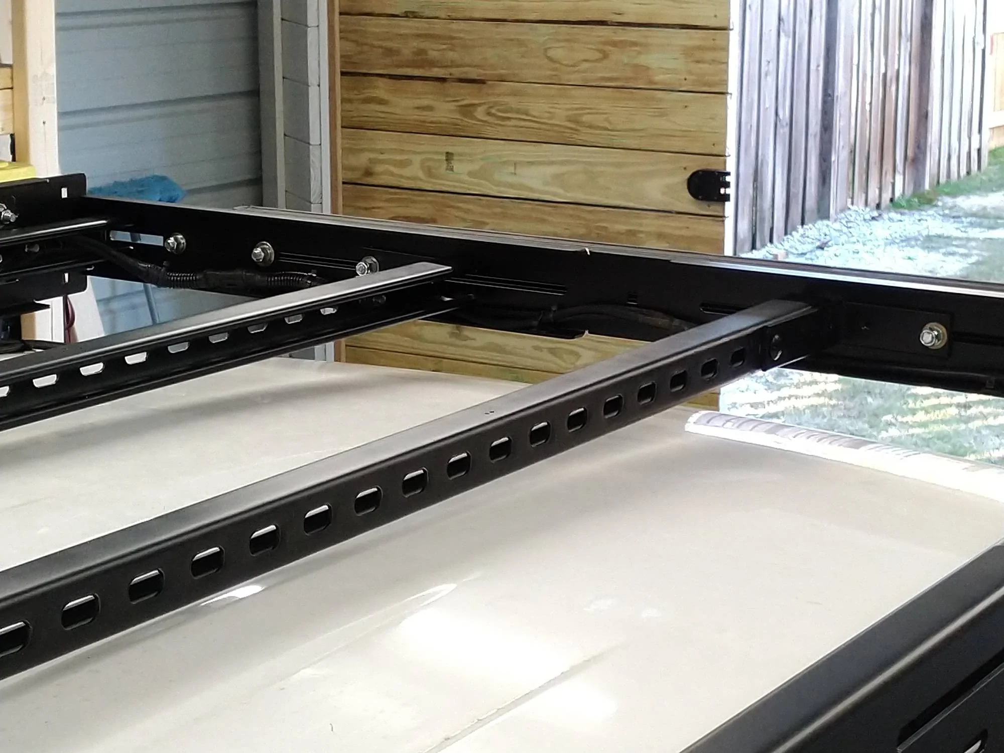
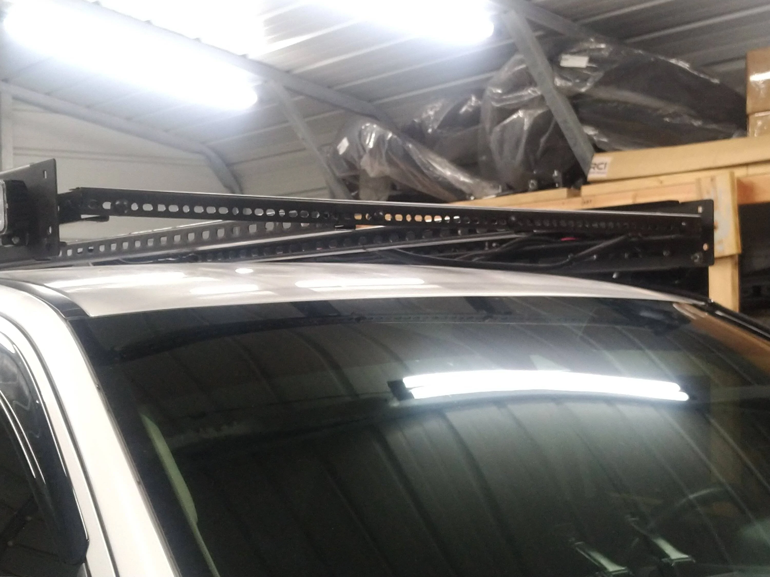
I will also be shortening my rack from 10 feet, to 8 feet. This is mostly to address hood glare from top mount lights, but also has a secondary purpose of pushing the span of cantilever back much further. Currently there is roughly 5 feet of the rack (rear portion) that is sub beams being supported completely by a sub frame which is in turn connected to my bed rack by numerous hard contact points. The other five feet (front portion) is supported only by the steel sub beams and two hidden "feet" located around the B-pillar area of the roof. These feet consist of 2" wide and 1" thick rubber stereo cabinet feet that rest over the gutter area. They connect to the outside sub beams via a simple nut and bolt system that makes them adjustable in height. They are adjusted so they provide enough upward tension that the sub beams can not longer "bounce" under heavy movement. I originally thought going to a unistrut sub beam system would be strong enough to withstand deflection on the overhang, but it just wasn't happening.

So the new front modification will have the overall platform length ending at the B pillar area, instead of at the front wind shield line. This will eliminate 2 feet of 5 feet of deflection area.

So here is my question; How do you decide when to use additional weight to counter deflection on non-static loads vs not? I have two choices for the new front sub panel beam I meantioned before. Another piece of unistrut, or a simple thin gauge steel piece of angle. Do I want to keep the front as light as possible to combat deflection, or use weight as an ally to counter balance against deflection. The unistrut is considerably more heavy than the angle steel piece I can use.

Secondary question; Does my question make any sense? /derp
Sponsored

 
Last edited:

Jhbryaniv

Well-Known Member
First Name
John
Joined
Sep 19, 2022
Threads
5
Messages
2,788
Reaction score
7,470
Location
Colorado
Vehicle(s)
2023 Ranger Tremor
Vehicle Showcase
1
Deflection will occur in all things...

Do you have the drawing in a cad program?

For my clarification - when you say "counter balance", what do you mean?
 
OP
OP
OFC Ranger

OFC Ranger

Well-Known Member
First Name
Jack
Joined
Aug 3, 2020
Threads
297
Messages
5,019
Reaction score
13,926
Location
Georgia
Vehicle(s)
ZR2
Deflection will occur in all things...

Do you have the drawing in a cad program?

For my clarification - when you say "counter balance", what do you mean?

Weight to fight back against deflection, or in simpler terms for my application; fight back against bounce.

It could be a double edged sword which is ultimately what I am trying to decide on; does more weight amplify the possibility, or does more weight help deter it.

I know the basic laws of physics say the bigger something is, the harder it is going to transfer force when moving, but also that the bigger something is, the more force it takes to get it moving.

I just don't know if there is a preferred choice on the matter in my specific application, or some sort of sweet spot.

Better description, put a plastic ruler on the edge of a table with half on the table and half hanging off.

Slap the end, that is the basics of what I am battling. Not exactly a 1:1 comparison, but you get the idea in general.

Another visual. The red marked section, if without the hidden support feet near the B pillar, is completed free floating. Now obviously its not bouncing like a plastic ruler, but bounce is present on hard impacts (think pot hole for example). Its not anything earth shattering, however it is enough to be visually seen, even if its only a half an inch of movement or less.

This is not good because 1.) It shows a flawed design 2.) Its not good for the sub beams long term. Some flex is good, that much flex is not.

100_0195.JPG


Sorry to answer your other question, I use SketchUp, not CAD. It is not at precise, but it is a great free tool for prototyping and initial visualization.

ranger_1.jpg


rtt_module1.jpg


rtt_module4.webp
 
Last edited:

Jhbryaniv

Well-Known Member
First Name
John
Joined
Sep 19, 2022
Threads
5
Messages
2,788
Reaction score
7,470
Location
Colorado
Vehicle(s)
2023 Ranger Tremor
Vehicle Showcase
1
Weight to fight back against deflection, or in simpler terms for my application; fight back against bounce.

It could be a double edged sword which is ultimately what I am trying to decide on; does more weight amplify the possibility, or does more weight help deter it.

I know the basic laws of physics say the bigger something is, the harder it is going to transfer force when moving, but also that the bigger something is, the more force it takes to get it moving.

I just don't know if there is a preferred choice on the matter in my specific application, or some sort of sweet spot.

Better description, put a plastic ruler on the edge of a table with half on the table and half hanging off.

Slap the end, that is the basics of what I am battling. Not exactly a 1:1 comparison, but you get the idea in general.
I think in basic terms you want to have taller supports - it is an I-beams height that provides resistance to deflection.

A modification of the ruler hanging off a table, if you rotate the ruler 90* so it was really skinny, but tall the "beam" would be more willing to go side to side instead of up and down. That is an extreme demonstration of the trade off of height vs width. If you could anchor the ruler to the table the ruler on its side would support more weight.

What length of bed do you have? 5 foot, right?
Crew cad?

What material are you planning to use? Unistrut as you mention above?

I Dont remember the math right now... Damn whiskey...

Square tube might make a good material choice - as it has an additional wall vs Unistrut for a similar footprint. However, it Might be negligible to use Unistrut facing like a u or an n... square tube adds additional weight...

CAD? I ask because some on here might have the ability to toss it into a simulation program...
 

P. A. Schilke

Well-Known Member
First Name
Phil
Joined
Apr 3, 2019
Threads
149
Messages
7,083
Reaction score
37,188
Location
GV Arizona
Vehicle(s)
2019 Ranger FX4 Lariat 4x4, 2020 Lincoln Nautilus, 2005 Alfa Motorhome
Occupation
Engineer Retired
Vehicle Showcase
1
Weight to fight back against deflection, or in simpler terms for my application; fight back against bounce.

It could be a double edged sword which is ultimately what I am trying to decide on; does more weight amplify the possibility, or does more weight help deter it.

I know the basic laws of physics say the bigger something is, the harder it is going to transfer force when moving, but also that the bigger something is, the more force it takes to get it moving.

I just don't know if there is a preferred choice on the matter in my specific application, or some sort of sweet spot.

Better description, put a plastic ruler on the edge of a table with half on the table and half hanging off.

Slap the end, that is the basics of what I am battling. Not exactly a 1:1 comparison, but you get the idea in general.

Another visual. The red marked section, if without the hidden support feet near the B pillar, is completed free floating. Now obviously its not bouncing like a plastic ruler, but bounce is present on hard impacts (think pot hole for example). Its not anything earth shattering, however it is enough to be visually seen, even if its only a half an inch of movement or less.

This is not good because 1.) It shows a flawed design 2.) Its not good for the sub beams long term. Some flex is good, that much flex is not.

100_0195.JPG
Hi Jack,

you have not given much in the way of loading info on the cantilevered part of the structure, but where the cantilever begins will be your weakest point. Since you are worried about cyclic fatique vs monotonic yield, this is where you need gussets or a flat piece of steel the runs most of the overhang and ties back to the main supported structure This flat steel should be taller than the side of the frame material (This can be added separately later of you discover you need reinforcement. If I was still working we would do this analysis based on your load case and likely take the load times 1.5g for a safety factor. Since I do not have that capability I can't really comment further, but the design appears quite robust. Now about Grade of bolt. If the bolts are in Shear, Grade 5 is better. If the bolts are to clamp two surfaces together, then Grade 8 is better Grade 5 tolerates clamping but is way better in shear than "brittle" Grade 8...

Best,
Phil


OP
OP
OFC Ranger

OFC Ranger

Well-Known Member
First Name
Jack
Joined
Aug 3, 2020
Threads
297
Messages
5,019
Reaction score
13,926
Location
Georgia
Vehicle(s)
ZR2
I think in basic terms you want to have taller supports - it is an I-beams height that provides resistance to deflection.

A modification of the ruler hanging off a table, if you rotate the ruler 90* so it was really skinny, but tall the "beam" would be more willing to go side to side instead of up and down. That is an extreme demonstration of the trade off of height vs width. If you could anchor the ruler to the table the ruler on its side would support more weight.

What length of bed do you have? 5 foot, right?
Crew cad?

What material are you planning to use? Unistrut as you mention above?

I Dont remember the math right now... Damn whiskey...

Square tube might make a good material choice - as it has an additional wall vs Unistrut for a similar footprint. However, it Might be negligible to use Unistrut facing like a u or an n... square tube adds additional weight...

CAD? I ask because some on here might have the ability to toss it into a simulation program...

Yes 5 foot crew cab. You are correct square tube would be better, but that is not a cost, nor a waste of existing design I am willing to take yet. But you bringing that up reminded me to say I have the exact same concerns and will be doing one of two things.

Option A: Adding some "fourth wall" mending plates/brackets at the cantilever point and forward on the unistrut support beams.

Option B: Flip the entire beam supports so the "open walled" portion is face down or face up. The only reason they are not because the pre-cut slots in unistrut just happen to be a super convenient for tying all the support panel brackets and everything together. I just need to not be lazy and drill those connection points if I flip and rotate the beams.

The material for the new front support beam is what is in question, do I go for another piece of unistrut, or something lighter, like a piece of angle steel. I have both types sitting in my garage for use.
 

Trigganometry

Well-Known Member
First Name
Rick
Joined
Dec 4, 2020
Threads
153
Messages
5,833
Reaction score
25,359
Location
Massachusetts
Vehicle(s)
20 XLT scab 301A/tow 4X4 magnetic w/sport blackout
Occupation
Engineering
Lots of variables in your question. In simple terms deflection has more to do with base materials and their tensile strength in combination with shape. A U channel will flex a lot more than a box channel of the same sizing. An Aluminum rectangle extrusion would be lighter but way more rigid. The amount of overhang from rigid mounts is directly related to degrees of deflection to weight at the end of the length.

As an example. If you used 80/20 extrusion in the rectangle style your rigidity would be night and day to your current configuration
 
OP
OP
OFC Ranger

OFC Ranger

Well-Known Member
First Name
Jack
Joined
Aug 3, 2020
Threads
297
Messages
5,019
Reaction score
13,926
Location
Georgia
Vehicle(s)
ZR2
Hi Jack,

you have not given much in the way of loading info on the cantilevered part of the structure, but where the cantilever begins will be your weakest point. Since you are worried about cyclic fatique vs monotonic yield, this is where you need gussets or a flat piece of steel the runs most of the overhang and ties back to the main supported structure This flat steel should be taller than the side of the frame material (This can be added separately later of you discover you need reinforcement. If I was still working we would do this analysis based on your load case and likely take the load times 1.5g for a safety factor. Since I do not have that capability I can't really comment further, but the design appears quite robust. Now about Grade of bolt. If the bolts are in Shear, Grade 5 is better. If the bolts are to clamp two surfaces together, then Grade 8 is better Grade 5 tolerates clamping but is way better in shear than "brittle" Grade 8...

Best,
Phil
The only thing forward of the cantilever really are two rifle cases with some recovery gear, I would guestimate sub 75lbs and a speaker, which is a few pounds.

All bolt connection points are to secure two pieces together (or clamp as you say), but most of them do so in a horizontal position, so sheer is involved for sure.
 
OP
OP
OFC Ranger

OFC Ranger

Well-Known Member
First Name
Jack
Joined
Aug 3, 2020
Threads
297
Messages
5,019
Reaction score
13,926
Location
Georgia
Vehicle(s)
ZR2
Lots of variables in your question. In simple terms deflection has more to do with base materials and their tensile strength in combination with shape. A U channel will flex a lot more than a box channel of the same sizing. An Aluminum rectangle extrusion would be lighter but way more rigid. The amount of overhang from rigid mounts is directly related to degrees of deflection to weight at the end of the length.

As an example. If you used 80/20 extrusion in the rectangle style your rigidity would be night and day to your current configuration
Oh yes for sure, at the sacrifice of cost. Anything over 5 feet also suffers heavy shipping cost. I wanted to avoid anything in my design that would require mending peices together in the sub support systems.

Unistrut on the other hand is readily available at DIY stores at about $30 per 10 feet.
 

Jhbryaniv

Well-Known Member
First Name
John
Joined
Sep 19, 2022
Threads
5
Messages
2,788
Reaction score
7,470
Location
Colorado
Vehicle(s)
2023 Ranger Tremor
Vehicle Showcase
1
Not to be that guy but, have you considered welding some of the parts together...
 
OP
OP
OFC Ranger

OFC Ranger

Well-Known Member
First Name
Jack
Joined
Aug 3, 2020
Threads
297
Messages
5,019
Reaction score
13,926
Location
Georgia
Vehicle(s)
ZR2
Not to be that guy but, have you considered welding some of the parts together...
No, because this is purposefully a weld-less design for modularity and damage repair reasons.

Any one single component can be removed and replaced as needed.
 
OP
OP
OFC Ranger

OFC Ranger

Well-Known Member
First Name
Jack
Joined
Aug 3, 2020
Threads
297
Messages
5,019
Reaction score
13,926
Location
Georgia
Vehicle(s)
ZR2
@Trigganometry

Damn you, of course I went on Google on the off-chance a local place can get 80/20 and it looks like grainger has 8 foot @ $50 a pair I can order online and pickup at the local store.

But that would bring up another hot mess of problems, converting every component over to utilize 80/20. I would still have to drill some portions out no way I would trust those sliding T-nuts to support the vertical panels.
 

Trigganometry

Well-Known Member
First Name
Rick
Joined
Dec 4, 2020
Threads
153
Messages
5,833
Reaction score
25,359
Location
Massachusetts
Vehicle(s)
20 XLT scab 301A/tow 4X4 magnetic w/sport blackout
Occupation
Engineering
@Trigganometry

Damn you, of course I went on Google on the off-chance a local place can get 80/20 and it looks like grainger has 8 foot @ $50 a pair I can order online and pickup at the local store.

But that would bring up another hot mess of problems, converting every component over to utilize 80/20. I would still have to drill some portions out no way I would trust those sliding T-nuts to support the vertical panels.
I use the stuff all the time. So many options it will make you crazy! The in channel lock strips are very robust. They’ll hold 100’s of pounds when used in pairs or 3’s. The holes that run down the middle of the channels you can tap with 1/4-20 on a power drill and some light oil.

I did this corner flat screen TV mount using it. Pivots both ways so screen is flat on wall or at the 45’ angle out into the middle of the room. 65” TV with a sound bar on the bottom. Height adjustable and lock with 2 5/16-18 cap heads.

I think you could attach lengths of the double wide to your U channel if you had 8 fasteners on rigid runs you would be amazed how stiff it would get. Could mount another U channel to the ends for front tie together for your lights and stuff. Plenty of recesses to run cable too.

20707722-CAF0-4D82-B7C7-49EFD6A0E9CE.webp
 
OP
OP
OFC Ranger

OFC Ranger

Well-Known Member
First Name
Jack
Joined
Aug 3, 2020
Threads
297
Messages
5,019
Reaction score
13,926
Location
Georgia
Vehicle(s)
ZR2
I use the stuff all the time. So many options it will make you crazy! The in channel lock strips are very robust. They’ll hold 100’s of pounds when used in pairs or 3’s. The holes that run down the middle of the channels you can tap with 1/4-20 on a power drill and some light oil.

I did this corner flat screen TV mount using it. Pivots both ways so screen is flat on wall or at the 45’ angle out into the middle of the room. 65” TV with a sound bar on the bottom. Height adjustable and lock with 2 5/16-18 cap heads.

I think you could attach lengths of the double wide to your U channel if you had 8 fasteners on rigid runs you would be amazed how stiff it would get. Could mount another U channel to the ends for front tie together for your lights and stuff. Plenty of recesses to run cable too.

20707722-CAF0-4D82-B7C7-49EFD6A0E9CE.webp

Yes that is an idea, using a couple to turn the unistrut into a completed square tube.

Although I do have a couple of lengths of 1/8th steel flat stock in my garage that could serve the same purpose. Run a length from right before the cantilever and down to the tips. Hmm...

I also think eliminating those 2 extra feet of deflection is going to help immensely.
 
OP
OP
OFC Ranger

OFC Ranger

Well-Known Member
First Name
Jack
Joined
Aug 3, 2020
Threads
297
Messages
5,019
Reaction score
13,926
Location
Georgia
Vehicle(s)
ZR2
Still plan to re-enforce the cantilever starting point with steel stock to complete the frame squaring, however I found out how to address the problem, without doing anything suggested in this thread. It was such a simple design error it is an embarrassment.

I just needed to add that front frame bar that ties the four support beams together, so they were all sharing the same physics among each other. Before hand, the two middle support beams tied to the front end via large 5mm L brackets that connected to the front panel. The problem was, these middle support beams still had a slight gap from the front panel, even when firmly attached via the brackets. This was a chink in the armor and allowing flex.

I cut down and used a slotted piece of angle iron and now all four beams are interconnected by being tightly drawn and bolted to that. The angle iron now having a lip on the top now "locks" the beams and prevents the angle iron from twisting or flexing under movement. It also forces all four beams to be of exact equal height with each other and no variations, even in centimeters to be present. The front panel now attaches to the front support. This killed any and all flex and also increased the force required for any bounce to occur by a substantial amount. No one beam can move at all now, without also requiring the other beams to move.

I should have known this and it pisses me off.

It may be a subtle difference in construction, but it changes the physics drastically. Old vs New (front panel not installed)

IMG_20211107_162001.jpg


IMG_20230131_180112.jpg
Sponsored

 
Last edited:


Top