Trying to understand 8 PIN HEADLIGHT PLUG WIRING

MartyL16

Member
First Name
Marty
Joined
Feb 12, 2022
Threads
6
Messages
23
Reaction score
6
Location
Chiang Mai Thailand
Vehicle(s)
2017 RHD FORD RANGER WILDTRACK 2.2 XLS
Occupation
Retired military
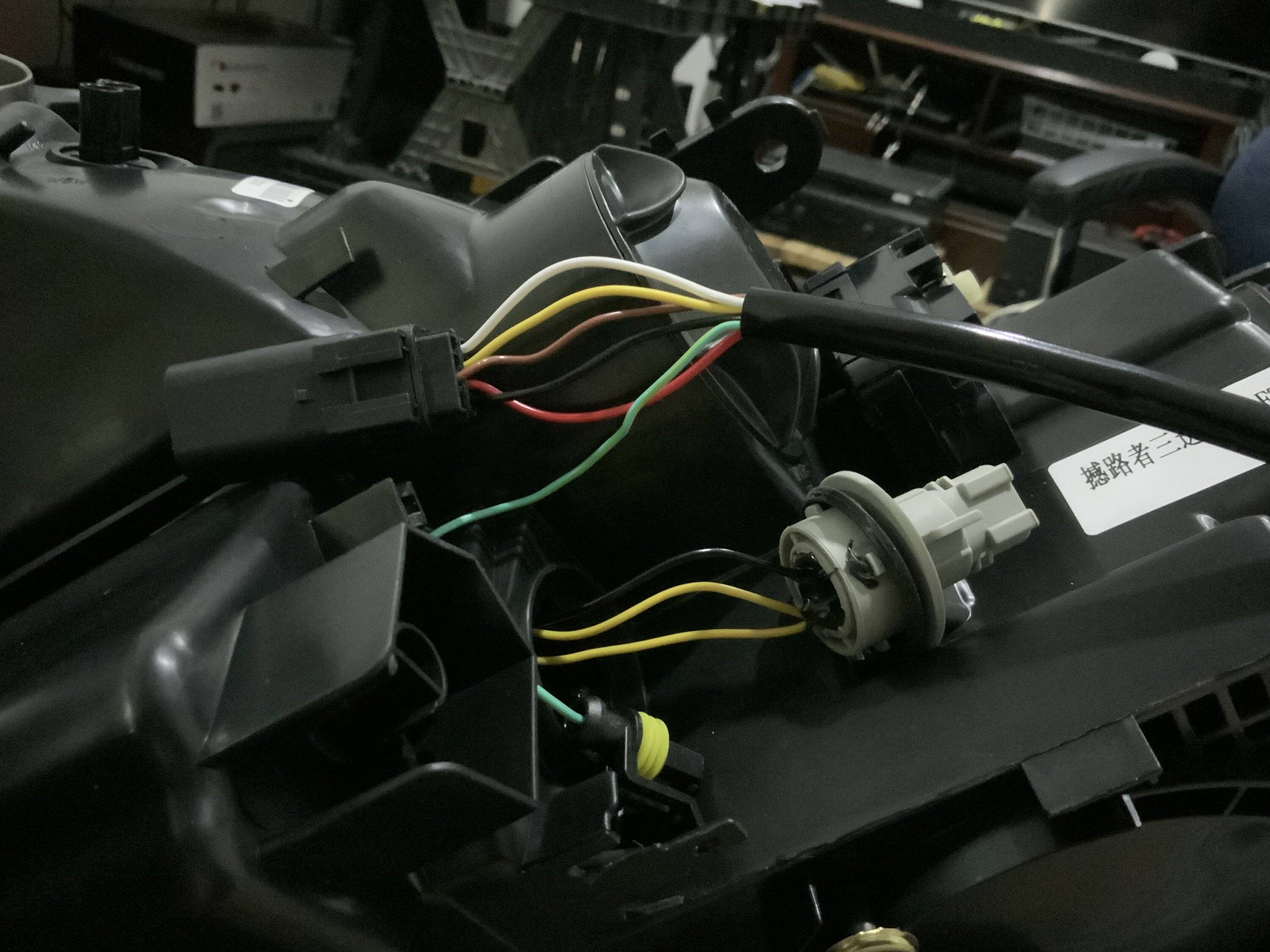
Hello, I am trying to understand the wiring for the 8 PIN FORD RANGER HEADLIGHT PLUG.

I am changing my wife’s 2019 RANGER HEADLIGHTS and the new headlights have that 8 PIN PLUG but not all wires to all PINS plus a ‘stand-alone’ GREEN WIRE.
I HOPE someone here can help with this problem.

Also in that picture you can see another 3 wire plug with 2 YELLOW and 1 BLACK WIRE. I believe these are for DRIVING LIGHT and TURN SIGNAL but haven’t TESTED THAT THEORY YET!

Picture attached:
THANKS

F160AC49-BEB7-4F43-BD12-DB84409FBA53.jpeg
Sponsored


airline tech

Well-Known Member
Joined
Aug 24, 2022
Threads
20
Messages
1,673
Reaction score
3,554
Location
Midwest - KS
Vehicle(s)
2022 Ranger Lariat-Super Crew, Cactus Gray
Occupation
Aircraft Tech
LH Headlamp as example - R/H Same

You have a 8 Pin connector that goes from factory harness to headlamp assy , within the headlamp assy you have a control module that splits out the harness and power and grounds, to the individual sources. So that 8-pin connector just feeds the Headlamp Control Module itself and that module is built inside the headlamp.

So with Forscan you are telling how you want the control module to distribute the power within the headlamp assy itself, thus this allows you to upgrade to the LED headlamps assemblies, without any wiring harness modifications, there is (1) known aftermarket option that has you splice/tap power from another source (fuse) (can't remember the brand) but if I recall it is not needed. I installed factory LED's with zero issues once I dove in with the correct settings in Forscan, there are a lot of conflicting posts on here on what to use. I did an extensive post on them.

Edit:

Sorry, just realized you have a Wildtrack, may not be the same wiring pinout as US Versions


onnector:
C1021
Description
HEADLAMP ASSEMBLY LH​
Color
Harness
14290​
Base Part #
part# N/A​
Service Pigtail
See Below​
Terminal Part Number
Service Part Number
Size
7C3T-14474-EADU2Z-14474-DA1.50
7C3T-14474-DA-2132208-
BU5T-14474-UADU2Z-14474-DA1.50
Pin
Circuit
Gauge
Circuit Function
Qualifier
Terminal Part Number
1​
GD125 (BK)​
14​
GROUND - FENDER FRONT RIGHT # 3RD POINT​
7C3T-14474-EA​
2​
CLF04 (BN-BU)​
16​
CTRL MOD. - BEAM LOW LEFT​
7C3T-14474-DA​
3​
CLF02 (GY-BN)​
16​
CTRL MOD. - BEAM HIGH LEFT​
7C3T-14474-DA​
4​
GD121 (BK-YE)​
16​
GROUND - FENDER FRONT LEFT # 2ND POINT​
7C3T-14474-DA​
5​
CLS06 (GN-OG)​
20​
CTRL MOD. - PARK FRONT LEFT OR FRONT/REAR LEFT​
BU5T-14474-UA​
6​
CLF61 (GY-BU)​
20​
CTRL MOD. - DAYTIME RUNNING LIGHT LEFT​
BU5T-14474-UA​
7​
CLS21 (BU-GN)​
20​
CTRL MOD. - TURN LAMP LEFT FRONT​
BU5T-14474-UA​
8​
GD121 (BK-YE)​
16​
GROUND - FENDER FRONT LEFT # 2ND POINT​
7C3T-14474-DA​
 
Last edited:
OP
OP

MartyL16

Member
First Name
Marty
Joined
Feb 12, 2022
Threads
6
Messages
23
Reaction score
6
Location
Chiang Mai Thailand
Vehicle(s)
2017 RHD FORD RANGER WILDTRACK 2.2 XLS
Occupation
Retired military
Thank you for your informative reply. Actually, Her Thailand made truck has no wiring harness. When I originally converted her headlights to LED, I had to change the HEADLIGHT PLUGS, and TURN SIGNAL PLUGS to use the new lights, so keeping that in mind, the 8 PIN plug only exists on these new lights and I haven’t begun to TEST these wires but will use the info you included and hopefully some of that will apply. Looking at my included picture you only see a few wires to that 8 PIN connector and that GREEN wire is a ‘stand-alone’ wire. I am thinking this headlight assembly uses only that GREEN WIRE for GROUND. The problem also is they gave me 2 additional BLACK WIRES with watertight plugs that ONLY FIT that GREEN WIRE PLUG but one of those BLACK WIRES has an INLINE FUSE and there is NO OTHER MATCHING PLUGS. So I have a problem.
 
OP
OP

MartyL16

Member
First Name
Marty
Joined
Feb 12, 2022
Threads
6
Messages
23
Reaction score
6
Location
Chiang Mai Thailand
Vehicle(s)
2017 RHD FORD RANGER WILDTRACK 2.2 XLS
Occupation
Retired military
Again thanks for your reply.
I made a mistake. I told you that ‘stand alone’ GREEN WIRE was probably GROUND. I WAS WRONG!
The SELLER told me to look in the box for additional BLACK WIRE with matching plug to that GRREN wire. Found that BLACK wire which has an ‘in-line fuse’ and a FEMALE PLUG to match the GREEN WIRE. I thought he said 2 wires but it is ONE WIRE with another ‘branching ‘off’ after the FUSE. Well that definitely proves it is a POSITIVE WIRE but still do not know if that connects to the POS on the battery or connected to a FUSE in the ENGINE FUSE BOX. My brain says POS BATTERY because of your explanation and the amperage rating of the in-line fuse.
 
OP
OP

MartyL16

Member
First Name
Marty
Joined
Feb 12, 2022
Threads
6
Messages
23
Reaction score
6
Location
Chiang Mai Thailand
Vehicle(s)
2017 RHD FORD RANGER WILDTRACK 2.2 XLS
Occupation
Retired military
LH Headlamp as example - R/H Same

You have a 8 Pin connector that goes from factory harness to headlamp assy , within the headlamp assy you have a control module that splits out the harness and power and grounds, to the individual sources. So that 8-pin connector just feeds the Headlamp Control Module itself and that module is built inside the headlamp.

So with Forscan you are telling how you want the control module to distribute the power within the headlamp assy itself, thus this allows you to upgrade to the LED headlamps assemblies, without any wiring harness modifications, there is (1) known aftermarket option that has you splice/tap power from another source (fuse) (can't remember the brand) but if I recall it is not needed. I installed factory LED's with zero issues once I dove in with the correct settings in Forscan, there are a lot of conflicting posts on here on what to use. I did an extensive post on them.

Edit:

Sorry, just realized you have a Wildtrack, may not be the same wiring pinout as US Versions


onnector:
C1021
Description
HEADLAMP ASSEMBLY LH​
Color
Harness
14290​
Base Part #
part# N/A​
Service Pigtail
See Below​
Terminal Part Number
Service Part Number
Size
7C3T-14474-EADU2Z-14474-DA1.50
7C3T-14474-DA-2132208-
BU5T-14474-UADU2Z-14474-DA1.50
Pin
Circuit
Gauge
Circuit Function
Qualifier
Terminal Part Number
1​
GD125 (BK)​
14​
GROUND - FENDER FRONT RIGHT # 3RD POINT​
7C3T-14474-EA​
2​
CLF04 (BN-BU)​
16​
CTRL MOD. - BEAM LOW LEFT​
7C3T-14474-DA​
3​
CLF02 (GY-BN)​
16​
CTRL MOD. - BEAM HIGH LEFT​
7C3T-14474-DA​
4​
GD121 (BK-YE)​
16​
GROUND - FENDER FRONT LEFT # 2ND POINT​
7C3T-14474-DA​
5​
CLS06 (GN-OG)​
20​
CTRL MOD. - PARK FRONT LEFT OR FRONT/REAR LEFT​
BU5T-14474-UA​
6​
CLF61 (GY-BU)​
20​
CTRL MOD. - DAYTIME RUNNING LIGHT LEFT​
BU5T-14474-UA​
7​
CLS21 (BU-GN)​
20​
CTRL MOD. - TURN LAMP LEFT FRONT​
BU5T-14474-UA​
8​
GD121 (BK-YE)​
16​
GROUND - FENDER FRONT LEFT # 2ND POINT​
7C3T-14474-DA​
I ordered a FEMALE 8 PIN so I do not have to cut wires. These headlights only have wires connected to 6 points. High beam and ground, Low beam and ground, PIN 7 on your list says TURN LAMP. PINS 5, 6, 8 ARE NOT WIRED. I will test sometime next week.
My guess is this headlight assembly ‘needs’ battery power to support the internal circuit board and that is what that separate GRREN WIRE with a FUSE is for. The OEM LIGHTS CONTROL ARM on the steering wheel has a SEPARATE BUILT-IN SWITCH TO TURN ON the foglights ( called parking lights) here. That leaves wire to pin 7 of no use in this truck (I think!)
I still have that other 3 wire plug with 1 BLACK wire and 2 YELLOW WIRES. LOOKING at that plug, the BLACK WIRE meets a ‘hidden’ pin I will assume is GROUND and each YELLOW WIRE has a separate purpose. 1 wire for DRIVING LIGHT, and 1 wire for TURN SIGNAL. If they ‘test-out’ as described then my ‘mystery is solved. As I said earlier, this truck was manufactured here in Thailand and when I converted her HIGH and LOW BEAMS to LED, then I had to wire them with their H3 and H11 plugs to connect to the new LED BULBS. The TURN SIGNAL,had its own 2 wire connection that remained the same and I added a DRIVING LIGHT/TURN SIGNAL to the front shell of the headlights but the Driving Light ONLY WORKS when you OPEN A DOOR and goes out until you TURN ON the HEADLIGHTS.
WHEN I add these new 3 PROJECTOR with DRIVING and TURN SIGNAL using the same LIGHT, I will wire the DRIVING LIGHT to a FUSE ADAPTER in the Engine Fuse Block. I have bought them as ‘pigtails’ that plug in where your FUSE BOX FUSE is moved to the duplex adapter ‘head. Then you will have the original FUSE to its circuit and another FUSE to the DRIVING LIGHT.
MY JOB IS ALMOST FINISHED and my ‘favorite shop’ will physically install these NEW ASSEMBLIES. I am too old to do that kind of labor. Brain works, body doesn’t!
The original Chinese Seller told me he was asking the factory for the wiring diagram but that never happened.
Sponsored


Top