Sponsored
8020 Extruded Aluminum Question
- Thread starter OFC Ranger
- Start date
- Watchers 3
Trigganometry
Well-Known Member
- First Name
- Rick
- Joined
- Dec 4, 2020
- Threads
- 153
- Messages
- 5,833
- Reaction score
- 25,359
- Location
- Massachusetts
- Vehicle(s)
- 20 XLT scab 301A/tow 4X4 magnetic w/sport blackout
- Occupation
- Engineering
It’s the shipping charges for oversized freight like this. In some cases it’s as much as the material itself. Having it delivered to a local Grainger outlet saves him that shipping charges.Also try McMaster Carr, they have various sizes and configurations up to 10ft.
OP
OP
OFC Ranger
Well-Known Member
- Thread starter
- #18
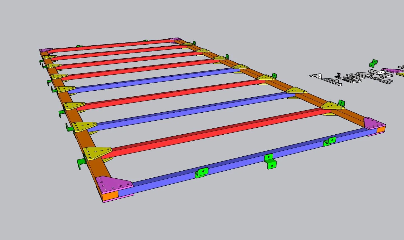
How is this looking so far for the primary subframe?
The 8ft beams will be 1020 and the cross beams (spaced at 12" apart) will be 1010. The blue highlighted ones will be supported directly on the RCI bed rack framing. The Z brackets will be for panel support.
Are the connection brackets I picked appropriate? I basically duplicated on top and bottom. Don't forget duraslat flooring will be laid on top providing even more rigid contact points.
The front cross beams might be shifted slightly to accommodate the factory shark fin antenna, but it should not be enough to compromise anything.
dmeyer302
Well-Known Member
- First Name
- Daniel
- Joined
- Feb 18, 2019
- Threads
- 21
- Messages
- 686
- Reaction score
- 1,648
- Location
- Carthage, MO
- Vehicle(s)
- 2016 Odyssey, 2021 F-150
- Occupation
- Mechanical Engineer
- Vehicle Showcase
- 1
Do you have any support above your cab or is this frame cantilevered over the cab? Not sure what your weights are here but I would suggest rotating the orange beams 90° for better rigidity. In such a case you would need to change at least part of your brackets, for example to something like this. Even if you don't rotate the beams, that style of bracket might help you to keep your floor in contact with the beams rather than floating on top of your plate brackets.How is this looking so far for the primary subframe?
The 8ft beams will be 1020 and the cross beams (spaced at 12" apart) will be 1010. The blue highlighted ones will be supported directly on the RCI bed rack framing. The Z brackets will be for panel support.
Are the connection brackets I picked appropriate? I basically duplicated on top and bottom. Don't forget duraslat flooring will be laid on top providing even more rigid contact points.
The front cross beams might be shifted slightly to accommodate the factory shark fin antenna, but it should not be enough to compromise anything.
Fordup
Well-Known Member
- First Name
- Ed
- Joined
- Jun 3, 2022
- Threads
- 17
- Messages
- 1,941
- Reaction score
- 9,598
- Location
- NY
- Website
- youtube.com
- Vehicle(s)
- 2022 Black Lariat Crew , 1966 Chevrolet Biscayne
- Occupation
- Retired YouTube Creator
Looking at that I think you are constantly going to have a water problem and a lot of extra weight from all the brackets and hardware that will also create a problem mounting the decking. Sure looks like a shop that is good at welding aluminum could put together a welded rack using cheaper aluminum tubing and then powder coat it any color you want for the same price range.How is this looking so far for the primary subframe?
The 8ft beams will be 1020 and the cross beams (spaced at 12" apart) will be 1010. The blue highlighted ones will be supported directly on the RCI bed rack framing. The Z brackets will be for panel support.
Are the connection brackets I picked appropriate? I basically duplicated on top and bottom. Don't forget duraslat flooring will be laid on top providing even more rigid contact points.
The front cross beams might be shifted slightly to accommodate the factory shark fin antenna, but it should not be enough to compromise anything.
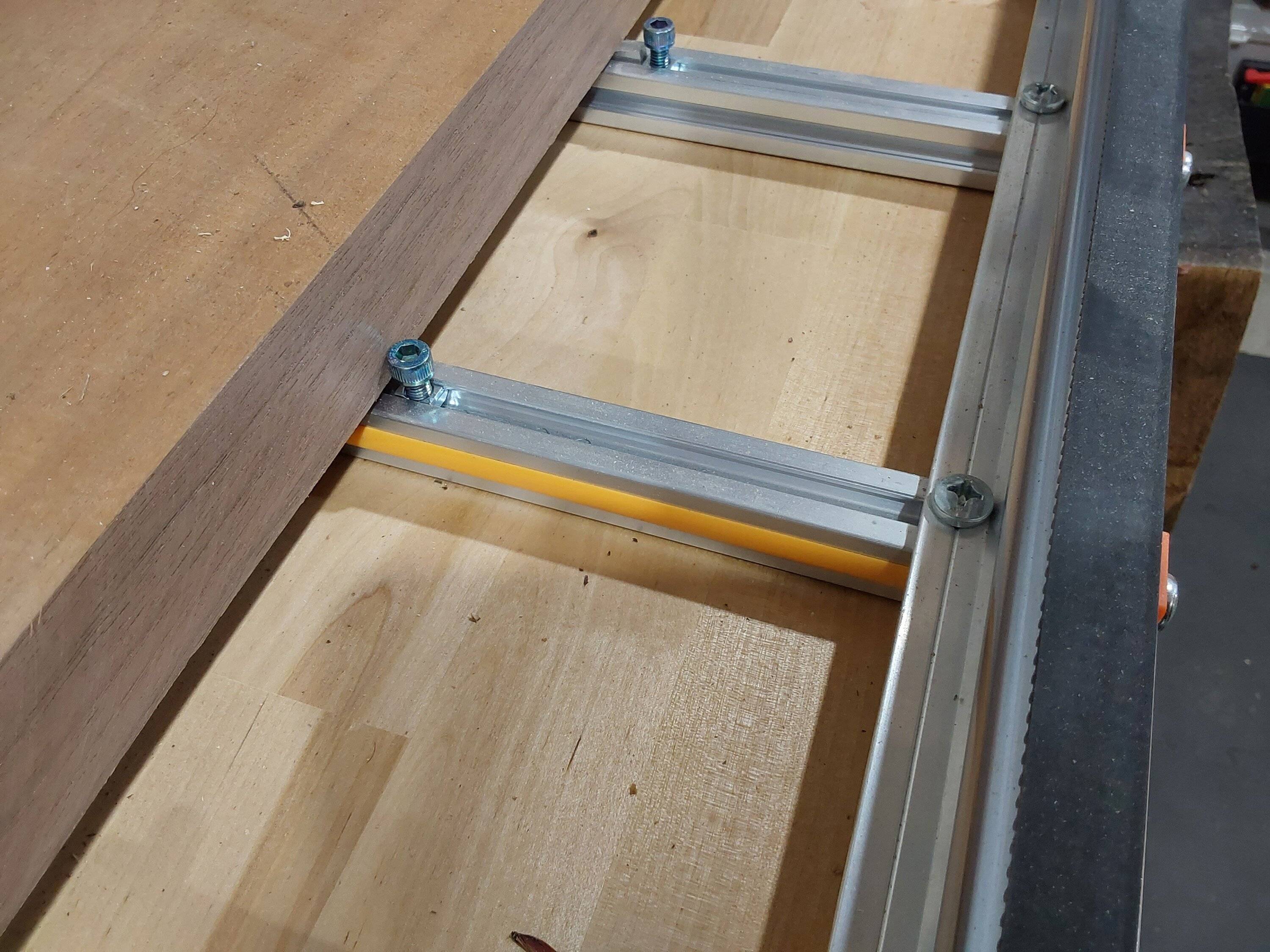
Instead of all the brackets I have tapped the center holes then drilled through the outer rails using One stainless socket head cap screw to bolt rails together. To eliminate twisting there are right angle brackets that can be slid in the slots and setscrews tighten it up with nothing visible looking at it. But I really think the slots will really hold water and eventually dust will fill them with mud using the slotted channel along with possible wind noise. Not sure of the mounting points , weight it must hold, or decking span ratings but it sure looks like a welded assembly would be lightest and easiest to keep nice. But that is just my opinion.
One other option could be eliminate cross pieces and just use lightweight aluminum trailer decking extrusion with an aluminum c channel on the sides.
Sorry not much help but that just doesn't look clean with all the hardware.
OP
OP
OFC Ranger
Well-Known Member
- Thread starter
- #21
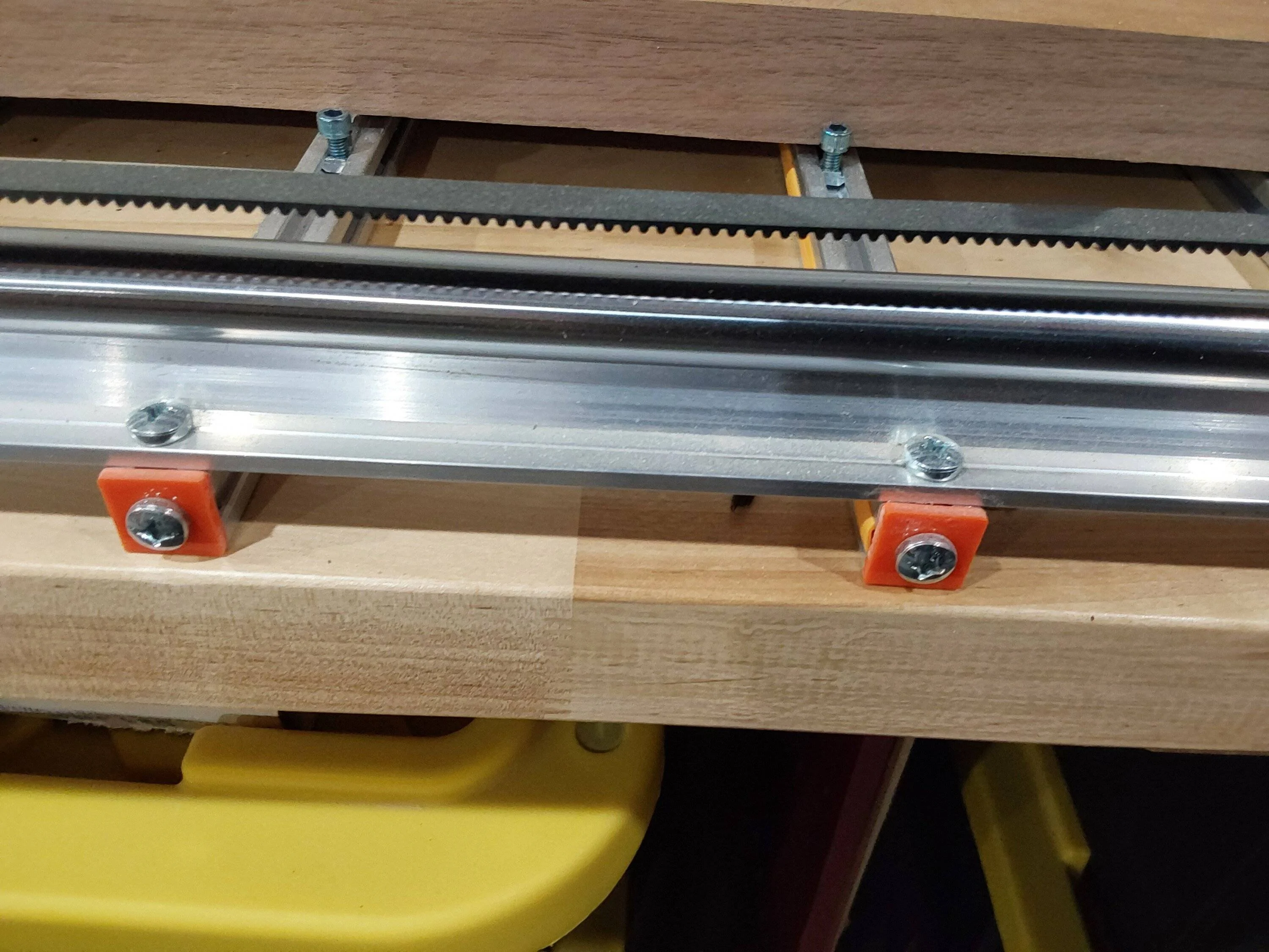
My current version, which is made of steel (unistrut channel) has two 2" x 1" rubber feet that rest on two layers of thick rubber pads, which in turn lays on the roof gutters. This eliminates the minor bounce/flex I was getting. This is also due to unistrut being more or less open on one side, which is far less rigid than something fully enclosed and square. It does have its advantages though. The reason I did not put the open side of the channel on the bottom was the main reason I designed with unistrut, the slots make its a robust modular system where every few inches becomes an easy attachment point instead of having to precision measure and drill.Do you have any support above your cab or is this frame cantilevered over the cab? Not sure what your weights are here but I would suggest rotating the orange beams 90° for better rigidity. In such a case you would need to change at least part of your brackets, for example to something like this. Even if you don't rotate the beams, that style of bracket might help you to keep your floor in contact with the beams rather than floating on top of your plate brackets.
I am looking to get away from steel and I was advised that 8020 would be rigid enough to allow free float of my design. My design will allow for feet to be installed again if required.
OP
OP
OFC Ranger
Well-Known Member
- Thread starter
- #22
None of my designs are waterproof. Any electric components run thought them are. Weight is a none issue as everything I use now is made from steel, including brackets.Looking at that I think you are constantly going to have a water problem and a lot of extra weight from all the brackets and hardware that will also create a problem mounting the decking.
The duraslat decking is not a problem as they are pre-drilled with holes to which the T nut bolts will line right up with the 8020 channels.
I made a no weld design on purpose. Damaged components can be easily swapped out without having to repair or mend existing damaged components. At this time I am not interested in a welded systems.Sure looks like a shop that is good at welding aluminum could put together a welded rack using cheaper aluminum tubing and then powder coat it any color you want for the same price range.
Gusset brackets are on the table for sure.Instead of all the brackets I have tapped the center holes then drilled through the outer rails using One stainless socket head cap screw to bolt rails together. To eliminate twisting there are right angle brackets that can be slid in the slots and setscrews tighten it up with nothing visible looking at it.
Open ends will be capped. Unused channels will receive rubber channel inserts. 8020 has all the accessories I need to minimized caking.But I really think the slots will really hold water and eventually dust will fill them with mud using the slotted channel along with possible wind noise.
I am going back to a cross beam design (version 1 from 2021) because it makes decking alignment very straight forward.One other option could be eliminate cross pieces and just use lightweight aluminum trailer decking extrusion with an aluminum c channel on the sides.
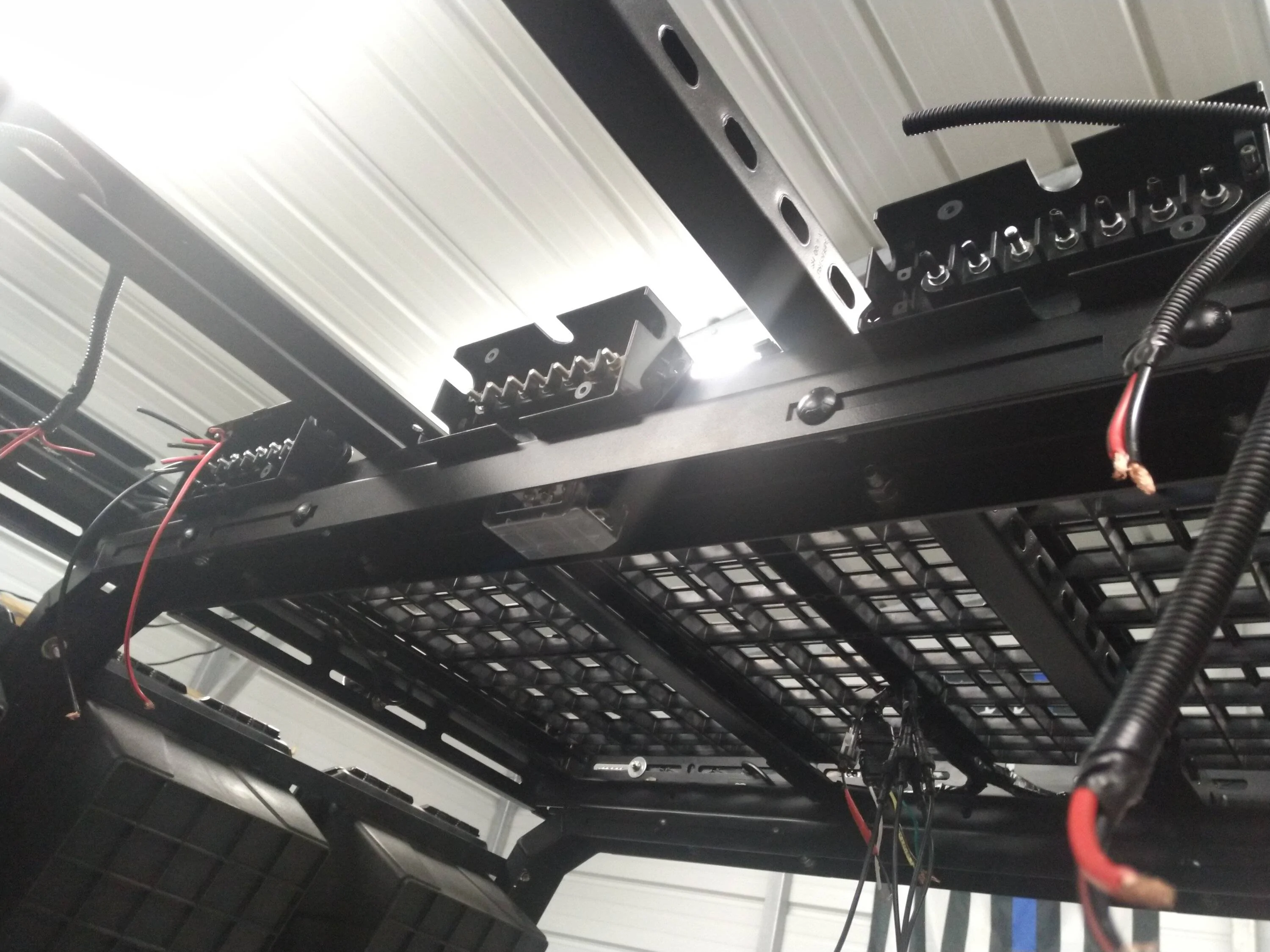
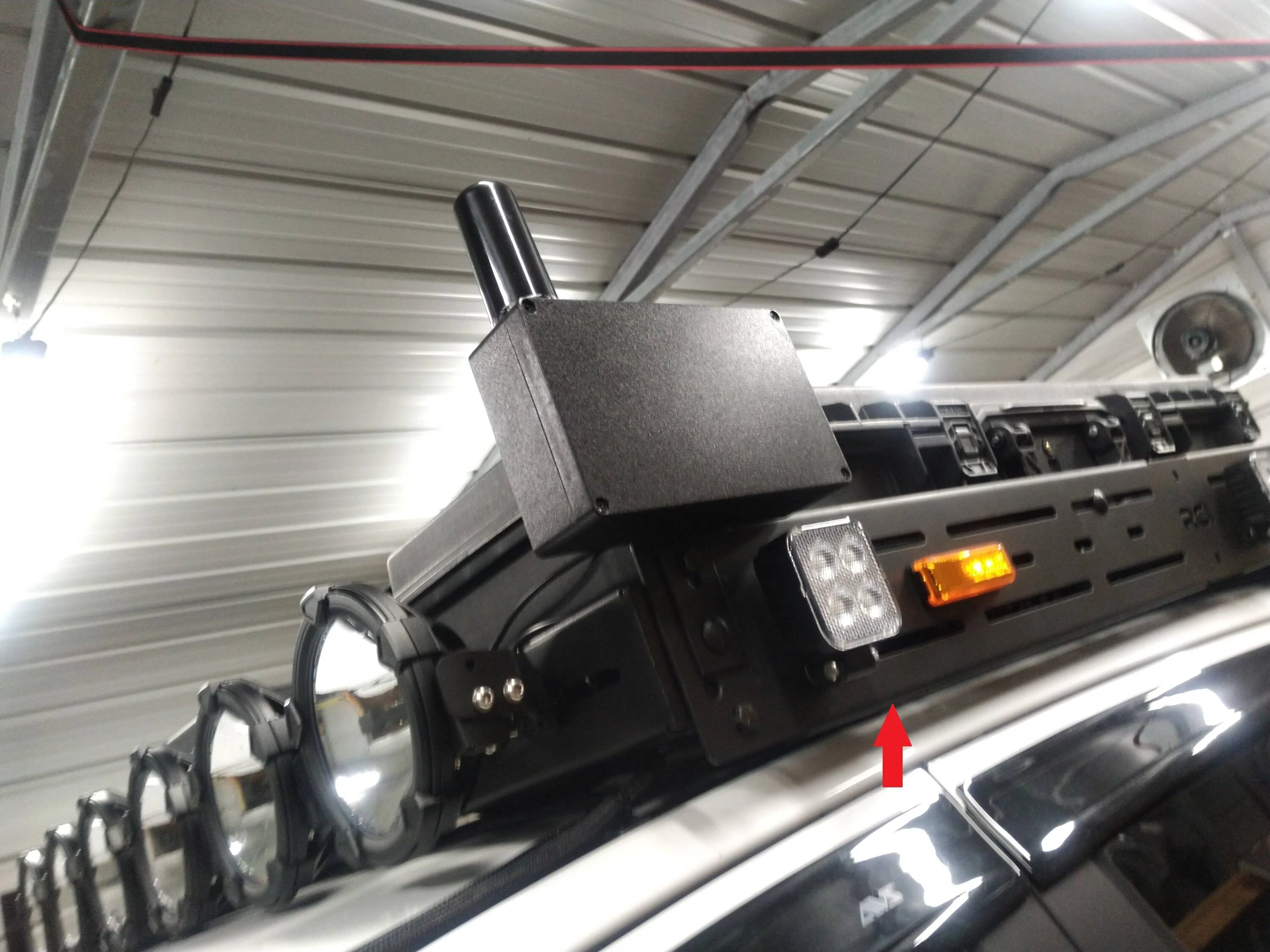
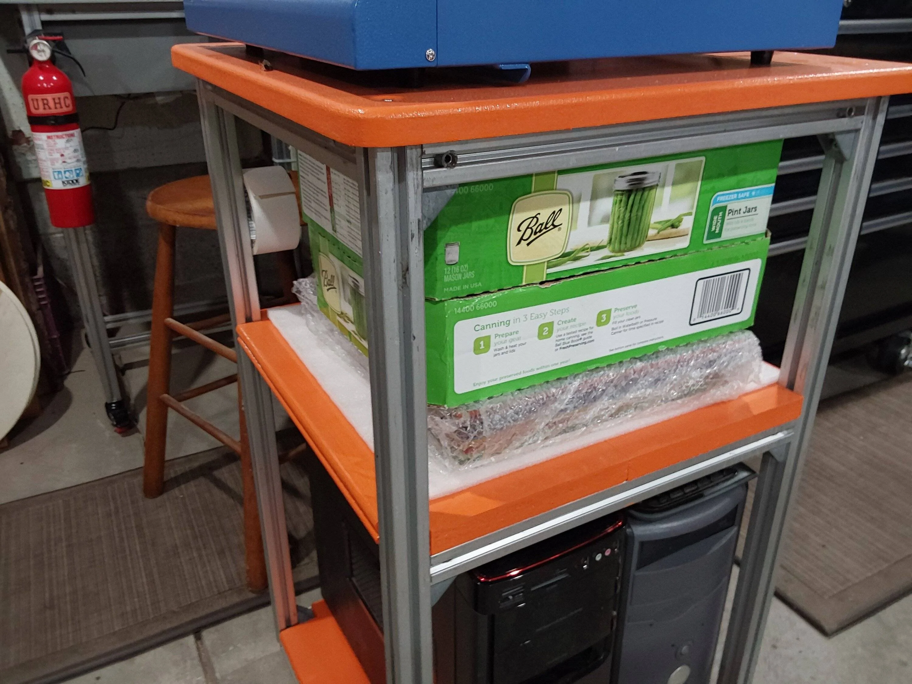
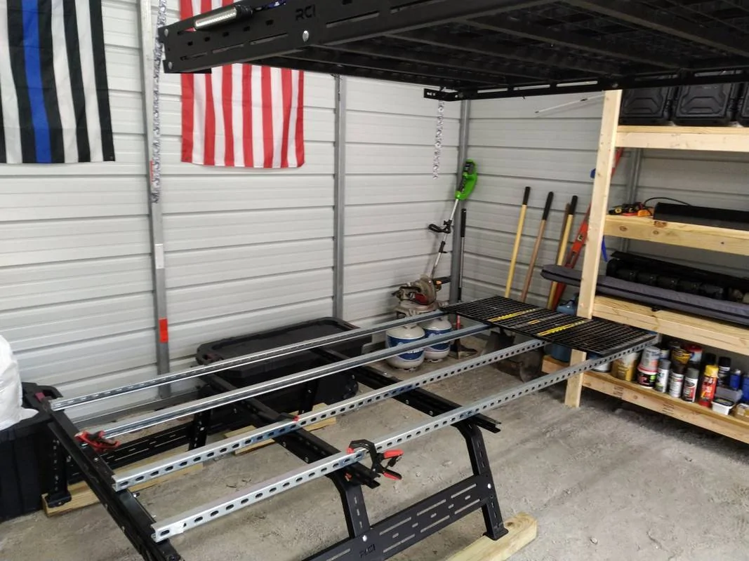
Understand a majority of hardware is invisible from the outside. My current version has all kinds of unistrut hardware. Here is a somewhat old photo (previous 10 foot version, I now built at 8 foot), but you get the idea. Only visible hardware are carriage bolts, which are paint matched.Sorry not much help but that just doesn't look clean with all the hardware.
I have become very proficient at hiding the guts of my contraptions since I opted for a weldless design.
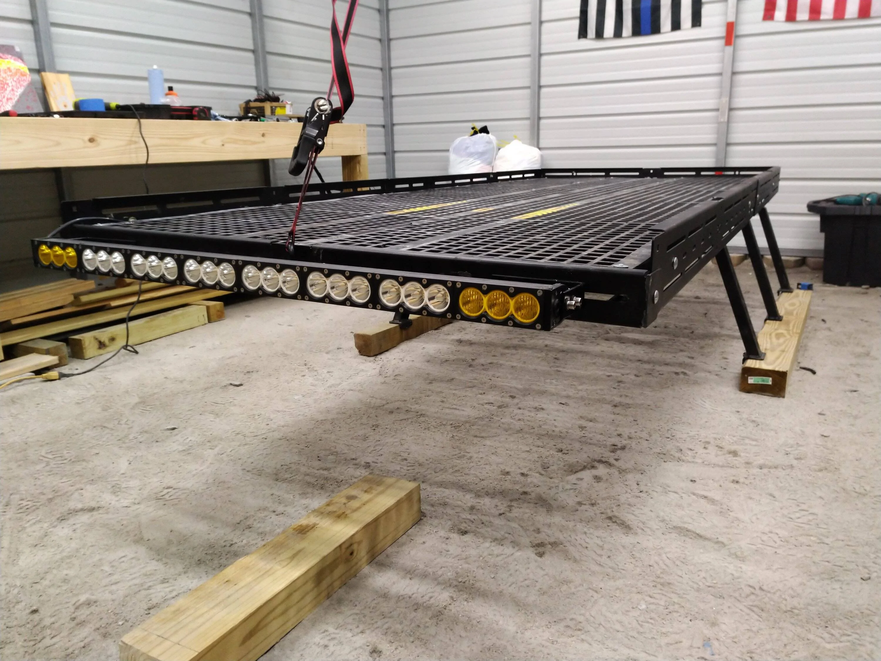
My weldless design works, its been in use for years now with no structural failures or signs of failure. Every once in a while I run into odd ball issue, but it was usually a small design fault on my part that is easily remedied.
My main focus now is weight reduction and a viable free float design without the need for forward support. I solve that, I create one of the markets only universal applications for a full over the cab roof platform.
I am looking at a possible business venture with a partner, so I am just checking out different paths to take. Weldless = less shipping restrictions = cheaper price tag.
The 8 foot beams will be the major hurdle in completely crushing the shipping costs. I am currently looking at tight tolerance folding solution for this.
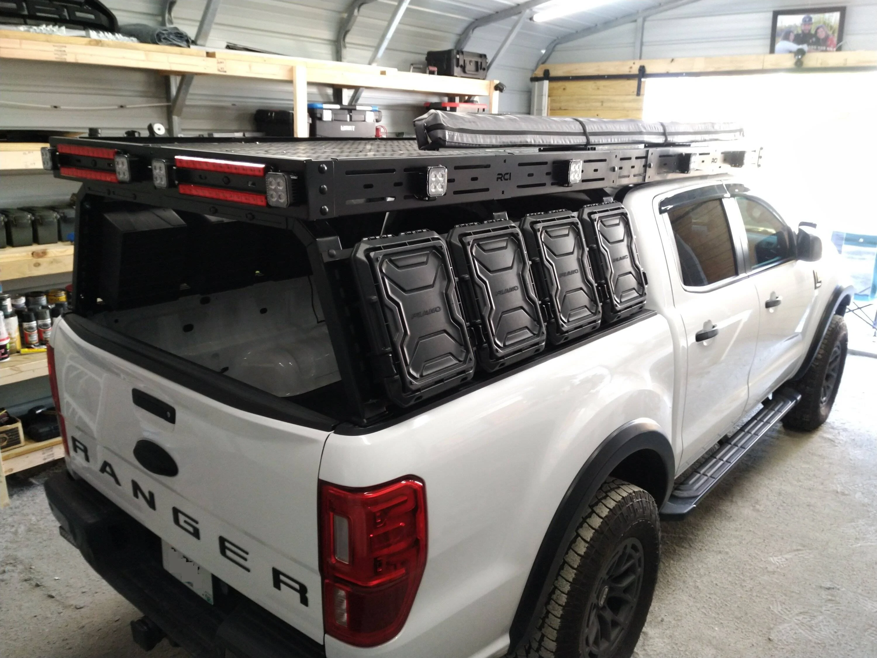
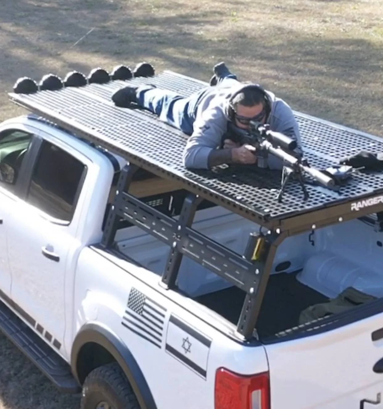
As long as the sub frame system is built correctly, Duraslat easily takes human weight.
Photo from way back on one of the earlier prototypes;
Last edited:
Fordup
Well-Known Member
- First Name
- Ed
- Joined
- Jun 3, 2022
- Threads
- 17
- Messages
- 1,941
- Reaction score
- 9,598
- Location
- NY
- Website
- youtube.com
- Vehicle(s)
- 2022 Black Lariat Crew , 1966 Chevrolet Biscayne
- Occupation
- Retired YouTube Creator
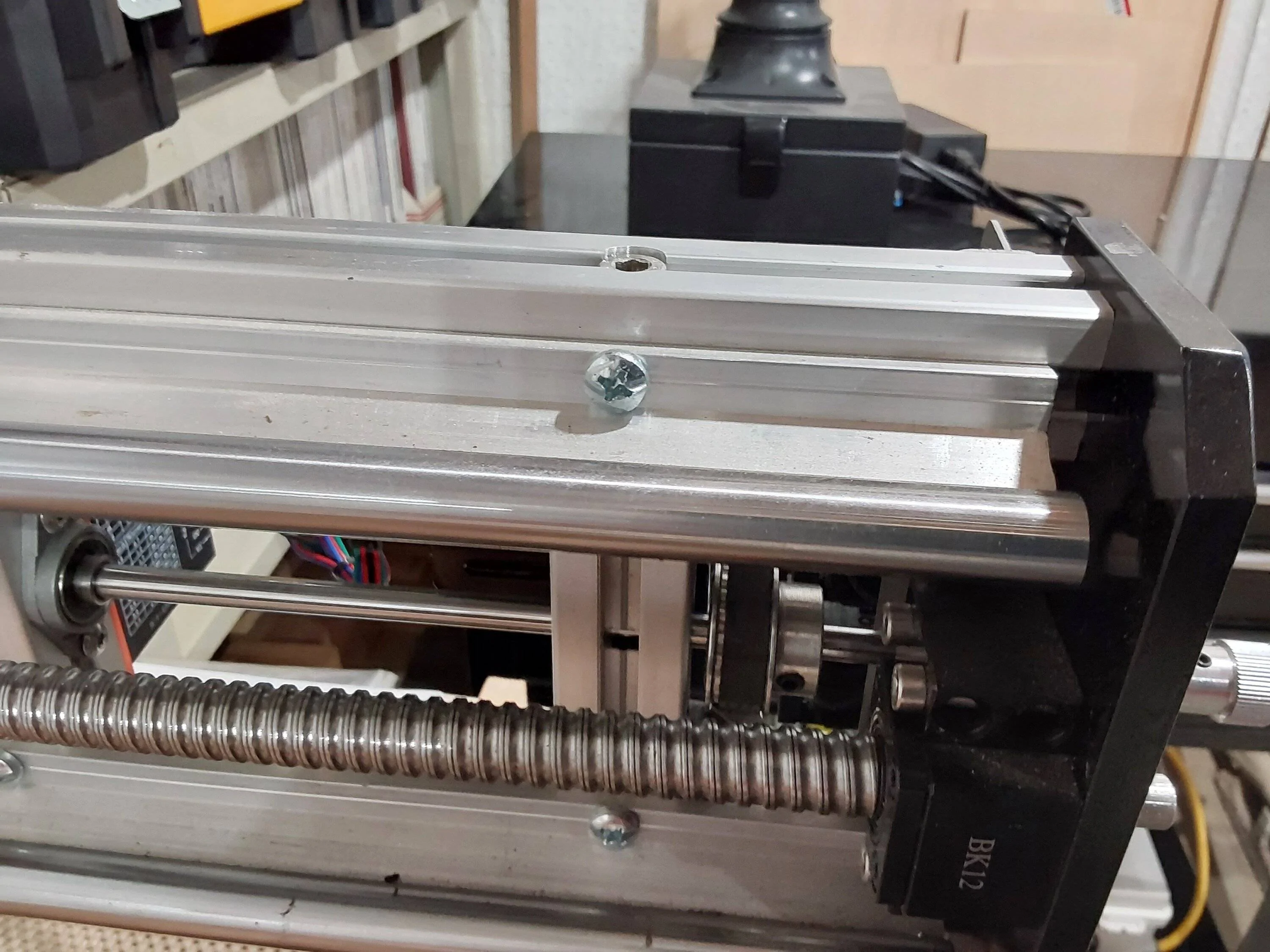
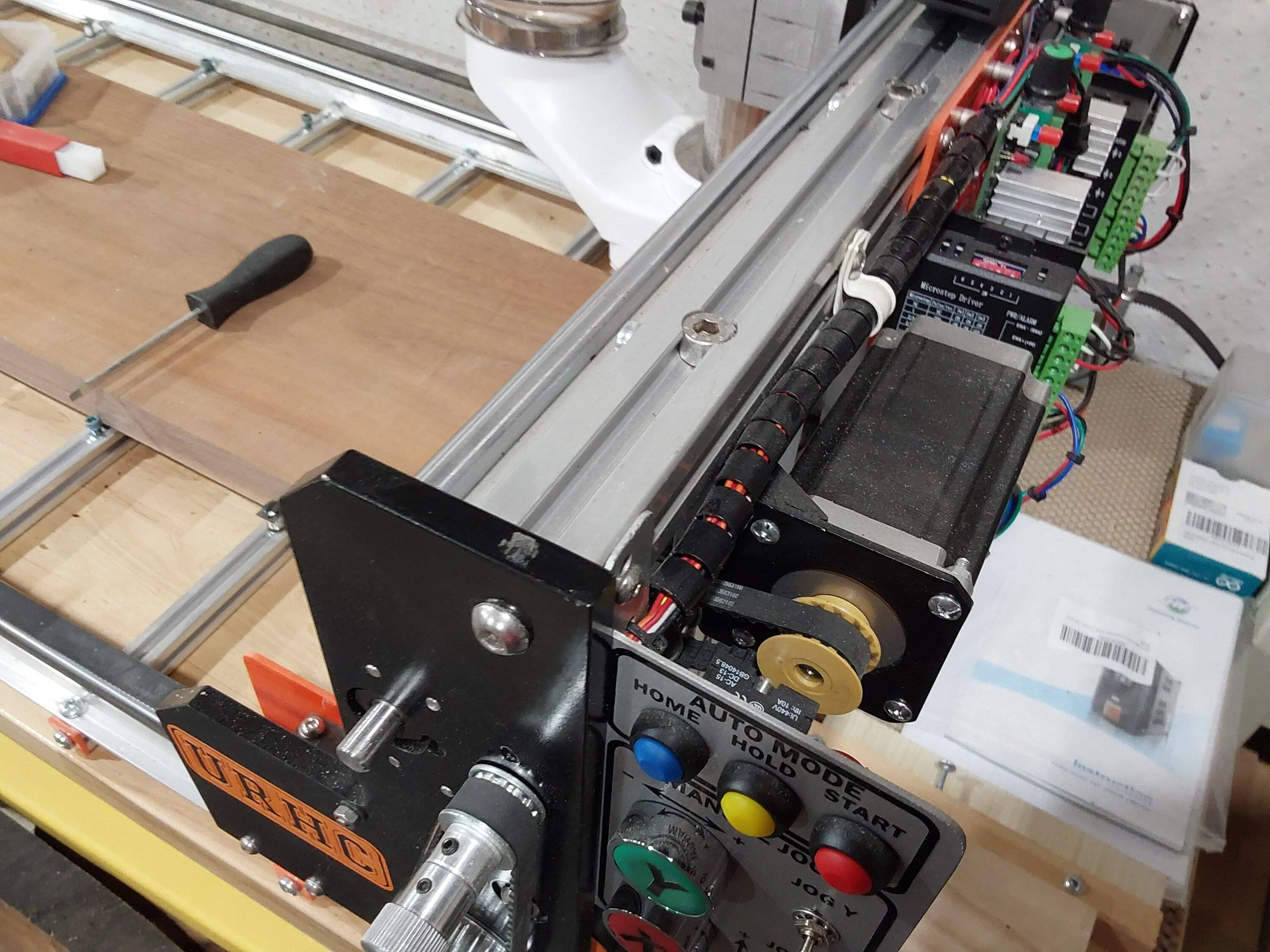
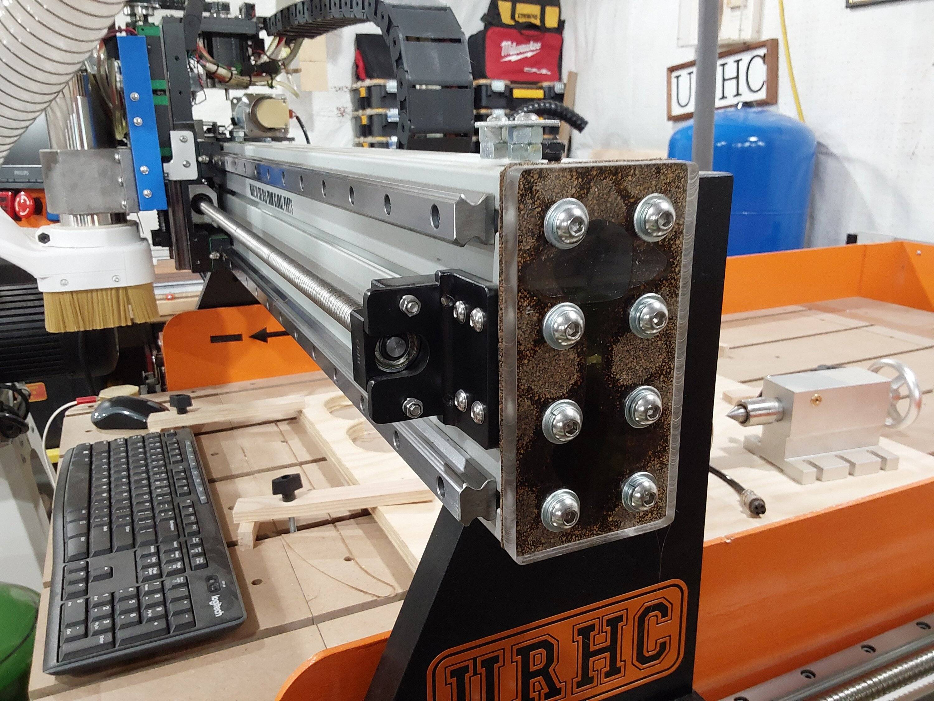
I use a lot of the 20mm and 30mm square. I find for any kind of structural applications 30 mm heavier wall is the best compromise. As I said the 30 mm can be cross drilled and bolted solidly together. Here's a machine I just built that shows the cross drilling

You can see the bolt from the top counterbored into the t area. A little loctite and it's very rigid with no brackets.
The filler strips are heat sensitive and expand and contract probably 1/2 inch total over 4 ft with temperature changes and are basically made for indoor applications to hide wires. You can get snap in aluminum ones but it's very expensive. It's easy to cap by tapping the center and cnc cut caps. Here are some pics of 20mm plugging and capping I do. For some reason the cap pic is at thee end.
You can see the inserts are not perfectly flat and temperature cycling will make the channels water and bug traps in my opinion
I also have many frames made from ot for supporting tools and they use factory connections that use a tapered lock with setscrews to pull the 90 deg joints tight. The factory options are like quick connect break down furniture joints.
They also use keyed right angle brackets for perfect alignment.
I also came up with a cooling system for the cnc router spindle on the machine I built that uses the extrusion as a water tank and cooling radiator. Just machined caps and cut gaskets.
It's really great stuff and they actually offer it with less t nut grooves that would help with water retention and the factory has many joinery options.
Another thing that could cause problems with decking is rigidly fastening it to aluminium with the nuts if you don't use oversized holes with rubber gaskets to allow it to move and keep it from rattling.
For just one person with that rack to mount it on wondering why you don't run the extrusions in the same direction as the unistrut to have less joints and possibly just use simple flat aluminium end caps screwed from the ends that would be easy to put your logo on. You could weld on a pocketed piece to keep the extrusions aligned and running front tobacco the rake would drain then constantly.
Just throwing out some ideas and not criticizing your work. Good luck.
OP
OP
OFC Ranger
Well-Known Member
- Thread starter
- #24
Nice.I use a lot of the 20mm and 30mm square. I find for any kind of structural applications 30 mm heavier wall is the best compromise. As I said the 30 mm can be cross drilled and bolted solidly together. Here's a machine I just built that shows the cross drilling
You can see the bolt from the top counter-productive into the t area. A little loctite and it's very rigid with no brackets.
The filler strips are heat sensitive and expand and contract probably 1/2 inch total over 4 ft with temperature changes and are basically made for indoor applications to hide wires. You can get snap in aluminum ones but it's very expensive. It's easy to cap by tapping the center and cnc cut caps. Here are some pics of 20mm plugging and capping I do
You can see the inserts are not perfectly flat and temperature cycling will make the channels water and bug traps in my opinion
I also have many frames made from ot for supporting tools and they use factory connections that use a tapered lock with setscrews to pull the 90 deg joints tight. The factory options are like quick connect break down furniture joints.
They also use keyed right angle brackets for perfect alignment.
I also came up with a cooling system for the cnc router spindle on the machine I built that uses the extrusion as a water tank and cooling radiator. Just machined caps and cut gaskets.
It's really great stuff and they actually offer it with less t nut grooves that would help with water retention and the factory has many joinery options.
Another thing that could cause problems with decking is rigidly fastening it to aluminium with the nuts if you don't use oversized holes with rubber gaskets to allow it to move and keep it from rattling.
For just one person with that rack to mount it on wondering why you don't run the extrusions in the same direction as the unistrut to have less joints and possibly just use simple flat aluminium end caps screwed from the ends that would be easy to put your logo on. You could weld on a pocketed piece to keep the extrusions aligned and running front tobacco the rake would drain then constantly.
Just throwing out some ideas and not criticizing your work. Good luck.
So running (4) 8 foot lengths vs (2) 8 foot lengths + cross beams is absolutely an option. That is how my current rack sub frame works with (4) unistrut channels and (1) 4 foot section on the front (for mounting purposes).
(again older photos, but you get the idea)
It just struck me that a cross beam system would be better for fighting twist in the sub frame.
I want to avoid drilling as much as possible. The end goal is for someone to open the box and assemble everything with just hand tools and proper locking material (ie; Loctite, etc etc). Keeping the system drill-less also serves the secondary purpose of modularity.
So take the cross beam design for example. Antenna location on roofs varies. Using just the basic T-nut setup, the cross beams could be shifted, however much, to accommodate such things, but also accommodate any other random thing on a vehicle I cannot account for.
Using a cross beam design also allows me to lower the center of gravity a bit. With a straight span setup (like I have now) - the minimum height of the entire rack will be based on the apex of the roof. With a cross beam setup I can shift the forward crossbeams slightly (spread them) so they cross before and after the highest apex of the roof. Now this might be a Ranger specific problem as other vehicles may have flatter roofs.
The same concept for side paneling mounts. The side mount brackets on my rack are not perfectly uniform in some places. In a few spots I had to shift them a few inches one way or the other to accommodate something, either a wiring loom, an AUX light, or what have you. Again, this sort of goes to the entire point of making everything possible on the rack user adjustable. In the past I cant count the amount of times I'd order a product, but it just didn't work because of some odd-ball reason with my intended use due to clearance issues, or positioning. That is why I wanted to set out with a goal to be able to overcome 99% of any weird issues like this.
As far as the rubber channels, I was actually looking at some plastic snap in versions that were decently priced per linear foot. I am OK with some parts being maintenance disposable over time.
Fordup
Well-Known Member
- First Name
- Ed
- Joined
- Jun 3, 2022
- Threads
- 17
- Messages
- 1,941
- Reaction score
- 9,598
- Location
- NY
- Website
- youtube.com
- Vehicle(s)
- 2022 Black Lariat Crew , 1966 Chevrolet Biscayne
- Occupation
- Retired YouTube Creator
I guess as I said before there are other options that may be better lasting, easier to assemble and cheaper to ship. 1 x 6 aluminum interlocking trailer decking would just take 8 lengths, 2 end channels, 2 rack mounts and a box of pop rivets that would assemble in an hour ship in a 6 x 8 x 8ft box the way it can be back to back stacked and be lighter then the decking alone with only a 1 inch total profile. Could actually add fiberglass bows and throw a camo tarp over everything with the ends open. Probably better aerodynamics then the grating. I have always been a Keep It Simple and foolproof person when I brought products to life. Just another idea for thought.
Sponsored
Similar threads
- Replies
- 15
- Views
- 2,092