OFC Ranger
Well-Known Member
- Thread starter
- #1
Some people play with legos, I like to play with electrical mapping and do so in the most analog way possible in the event of failure repairs. That means no fancy digital boxes to control channels or what channel does what (momentary, strobe, etc etc). If your expensive Six Shooter or Switch Pro setup has a failure you have three options;
1. Under Warranty Repair (you are also out of a control system for X amount of time)
2. Attempt Self Repair (higher than normal electronics know-how required)
3. Garbage Can
So I like building systems a novice (cause that is me) can service as required with some very basic knowledge.
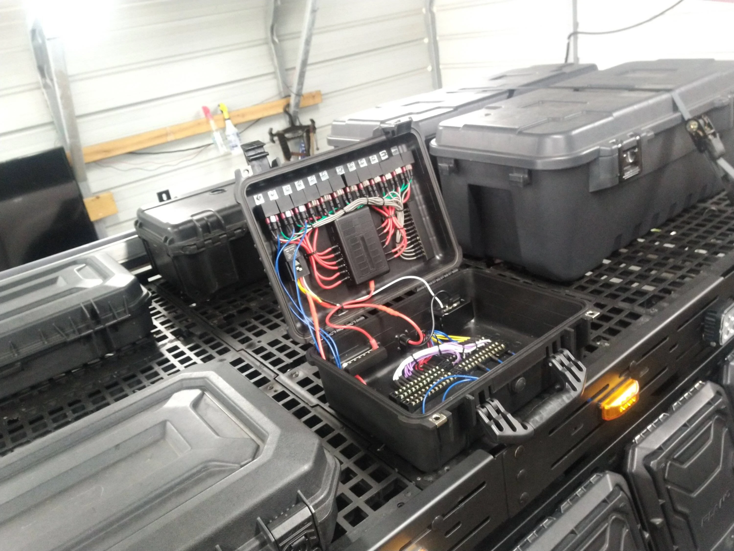
This project would be an example of no where to cram a control system under the hood or stowed away somewhere out of sight on the interior. Ideal for roof racks (which is what I am going to use it for) or truck beds. I've contemplated making these for sale, but for now its just for fun.
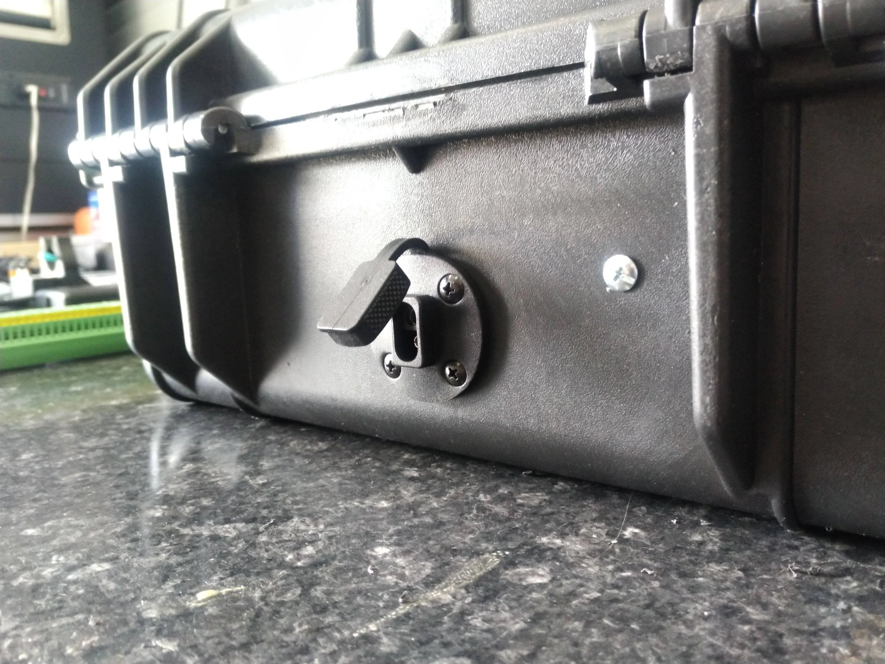
The case is from Harbor Freight - really no more basic structure different than a PLANO or PELICAN, but it was only $30.00 for the medium size variety. This particular setup will be quick disconnect, having only three entry points for ingress of wiring, both of which will be detachable.
A primary power and ground line will enter via SAE flush mount connector (disconnect 1) and then a 16 channel harness will be fed through a grommet/electrical gland (disconnect 2). A trigger harness (fed from button controller of choice) will also enter the same method (disconnect 3) That is it. Everything else will happen on the inside.
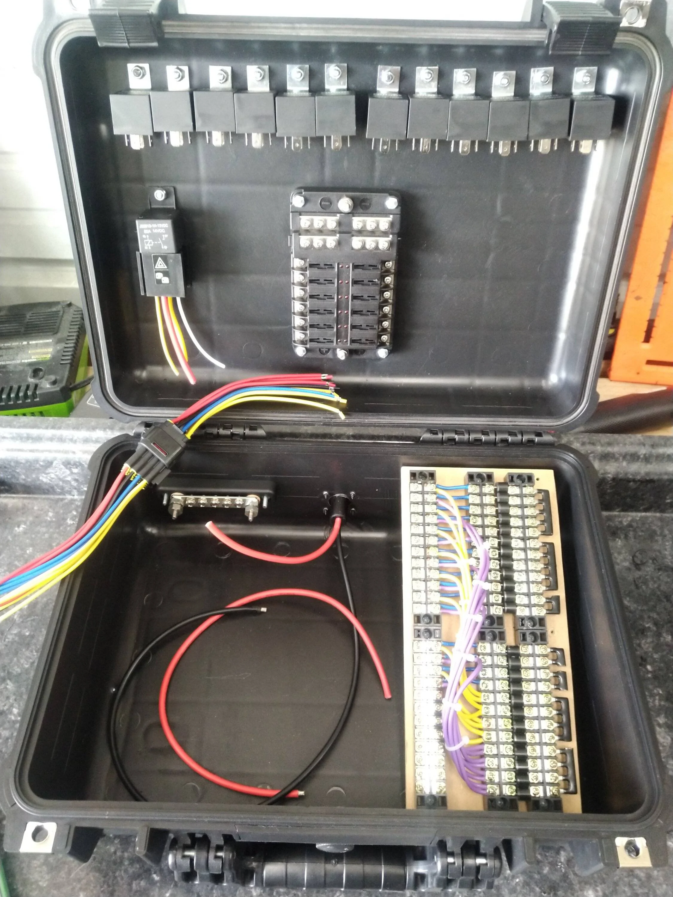
The main power line will go directly to an 80A relay. That relay will be triggered by keyed ignition. The 80A fuse will then send power to a power distribution bus bar. The main ground line will go straight to its own ground distribution bus bar.
The power and ground bus bar will then feed power to the fuse box. The remaining bus bar channels will be there "as needed" - like if you want to add a small switch and light inside the box as a simple example. The rest is pretty standard, the fuse box will then feed power and ground to 12 relays. Each relay will get its trigger line feed from the trigger line harness (in my case, 12 relays so 12 channels). The 12 relays will then send the power to a series of diode blocked one way terminals and travel onto the the 16 channel harness. The four extra channels in this case are for some other purposes.
* The one way diode blockers are what gives a single light the ability to receive multiple channel inputs without back feeding the other. IE; I can make one light have different functions for each diode blocked channel it interacts with. This also means you only need one single line from this point to the light.
Hoping to finish it by middle of next week, but its coming together now.
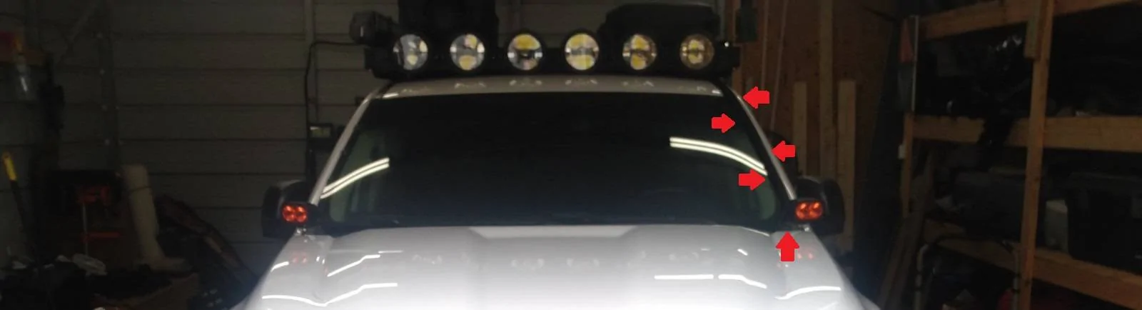
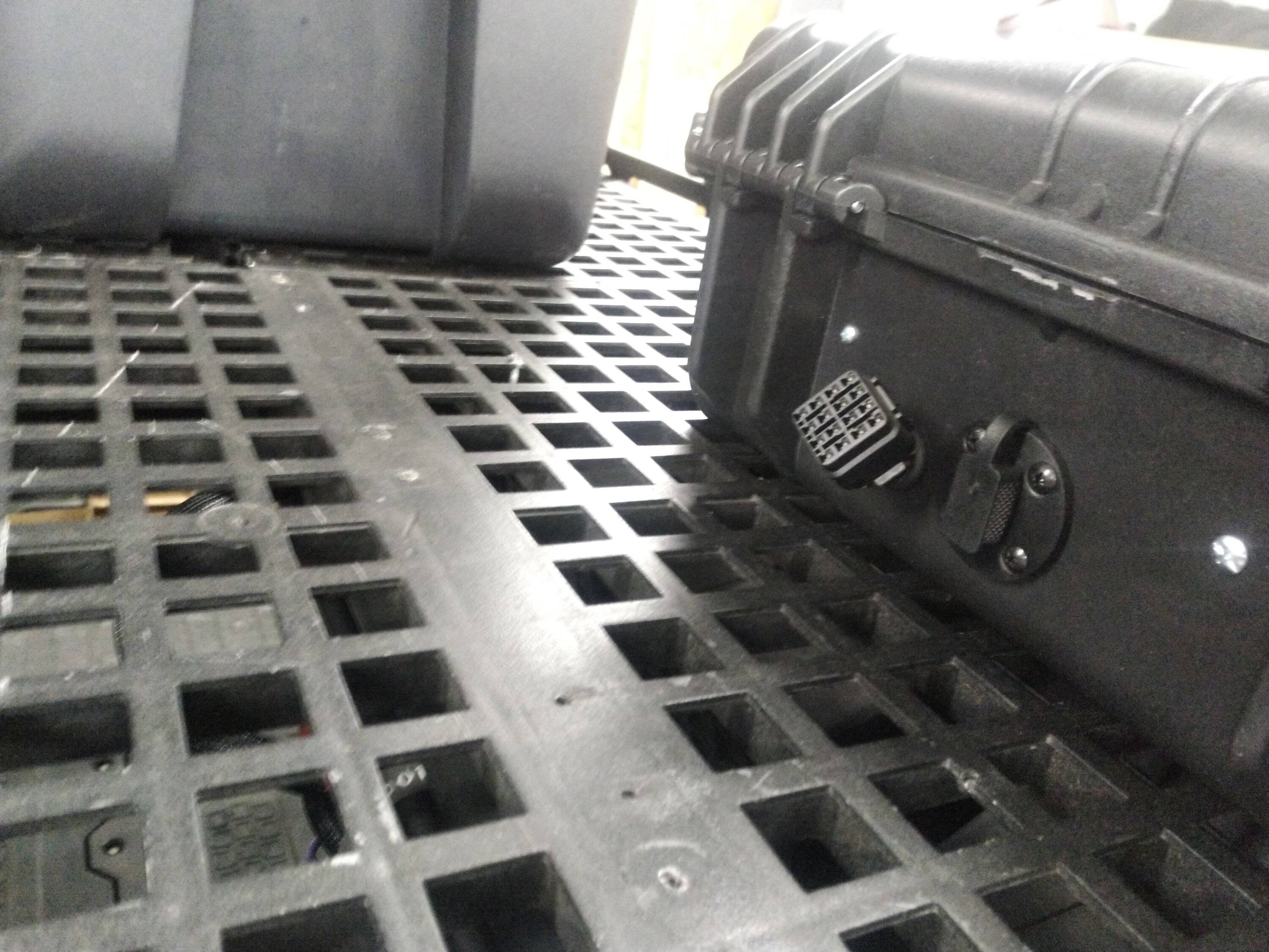
The first picture shows you the main power and trigger harness line. Or rather you can't really see it, but I've pointed it out. They are contained in a mesh loom that runs up the side of my wind shield on the outside. I wanted the most direct shot to the box up top as possible.


Disregard how wacky the relays look. They use oversized holes and when I am done they will be shifted and locked back down evenly.

1. Under Warranty Repair (you are also out of a control system for X amount of time)
2. Attempt Self Repair (higher than normal electronics know-how required)
3. Garbage Can
So I like building systems a novice (cause that is me) can service as required with some very basic knowledge.
This project would be an example of no where to cram a control system under the hood or stowed away somewhere out of sight on the interior. Ideal for roof racks (which is what I am going to use it for) or truck beds. I've contemplated making these for sale, but for now its just for fun.
The case is from Harbor Freight - really no more basic structure different than a PLANO or PELICAN, but it was only $30.00 for the medium size variety. This particular setup will be quick disconnect, having only three entry points for ingress of wiring, both of which will be detachable.
A primary power and ground line will enter via SAE flush mount connector (disconnect 1) and then a 16 channel harness will be fed through a grommet/electrical gland (disconnect 2). A trigger harness (fed from button controller of choice) will also enter the same method (disconnect 3) That is it. Everything else will happen on the inside.
The main power line will go directly to an 80A relay. That relay will be triggered by keyed ignition. The 80A fuse will then send power to a power distribution bus bar. The main ground line will go straight to its own ground distribution bus bar.
The power and ground bus bar will then feed power to the fuse box. The remaining bus bar channels will be there "as needed" - like if you want to add a small switch and light inside the box as a simple example. The rest is pretty standard, the fuse box will then feed power and ground to 12 relays. Each relay will get its trigger line feed from the trigger line harness (in my case, 12 relays so 12 channels). The 12 relays will then send the power to a series of diode blocked one way terminals and travel onto the the 16 channel harness. The four extra channels in this case are for some other purposes.
* The one way diode blockers are what gives a single light the ability to receive multiple channel inputs without back feeding the other. IE; I can make one light have different functions for each diode blocked channel it interacts with. This also means you only need one single line from this point to the light.
Hoping to finish it by middle of next week, but its coming together now.
The first picture shows you the main power and trigger harness line. Or rather you can't really see it, but I've pointed it out. They are contained in a mesh loom that runs up the side of my wind shield on the outside. I wanted the most direct shot to the box up top as possible.
Disregard how wacky the relays look. They use oversized holes and when I am done they will be shifted and locked back down evenly.
Sponsored
Last edited:
")