airline tech
Well-Known Member
- Joined
- Aug 24, 2022
- Threads
- 28
- Messages
- 4,458
- Reaction score
- 8,520
- Location
- Midwest - KS
- Vehicle(s)
- 2022 Ranger Lariat-Super Crew, Cactus Gray
- Occupation
- Aircraft Tech
- Thread starter
- #1
This is going to be a - add sections as I go and will update gradually, rather than the complete post at once as I am gathering info for the aftermarkets
Due to the great number of issues members are having with all Aftermarket Headlights, I wanted to attempt to find a resolution and to bring a full understanding of how differ in wiring and why they push the use of tapping a power source.
I do not have aftermarkets, but I did swap my Lariat (LED) Deleted headlamps (Halo's) for Factory LED Headlamps & Fogs to bring it back to how it was ordered.
I used the As-Built data files and crossed checked (Halo & LED) in the As-Built files for various VIN's and found that all (Halo) and all (LED) were set up differently.
I took the LED Lariat settings and made the As-Built changes as needed in the BCM.
So, I know exactly all As-Built Data files that need changed to swap from Halo's to Factory LED's - Simple and work Flawlessly.
So, we will start with ALL Rangers are wired the same (for lighting) the change occurs at the Headlight Assemblies themselves and how they are pinned out at the Headlight (Component Side)
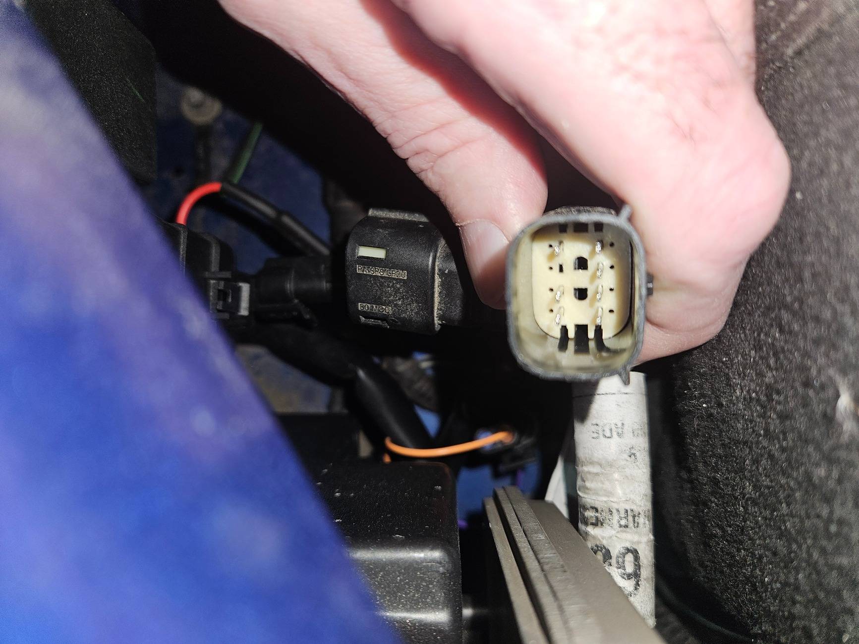
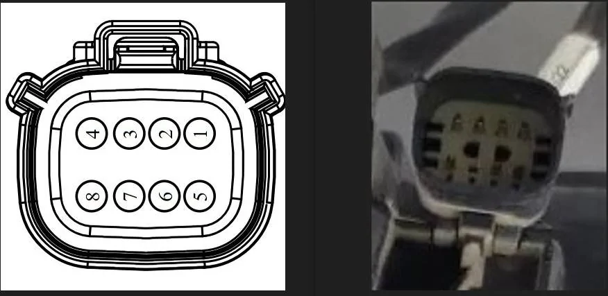
Here we have the Halo Headlight Connector (Harness Plug & Headlight Connector)
NOTE: Pin #6 is missing - this is due to the fact that the Halo's provide DRL Power to the Low Beam @ 50% Power
The BCM - is set the do this and no power is applied to PIN #6 (from the BCM to the Harness Connector)
Power for the Halo Headlamps from the BCM is as follows (As-Built Data) Specific:
I need to get my Forscan settings set back to OE (Halo) settings and actually VERIFY which of the following is TRUE
1. The BCM does not provide power on Pin #6 at all for the Halo (As-Built) settings
2. The BCM provides power to Pin #6 (Harness Side) but since it is deleted in the Headlight Connector - It Dead Ends
This is a valuable piece of information that is needed as this will truly tell me what the BCM is doing with power outputs.
Low Beam:
Power = Pin #2 (12 Volts)
Ground = Pin # 8
DRL:
Power = Pin #2 (6-Volts)
Ground = Pin # 8
High Beam:
Power = Pin #3
Ground = Pin #8
Parking Lights:
Power = Pin # 5
Ground = Pin # 1
Turn Signals:
Power = Pin # 7
Ground = Pin # 1
Ref: Note Pins 4 & 8 are spliced together (within the wire harness) Grounds
Halo Connector (Factory OE) - Pin #6 Missing on the Headlight (DRL-Circuit)
EDIT: UPDATE 2/28/25
---
I wanted to verify my above voltage (wire checks) for the factory Halo (BCM-As-Built) power
I reset all As-Builts back to Factory (OE) settings for the Halo's as they were installed.
DRL's (Only)
Initially I had 12 Volts on Pin 2 (Low Beam) and 12 Volts on Pin 5 (Park) but the sun was setting, and I think my Headlamps Triggered (ON)
Tried again (Today) in the full sun, no matter how I configured it, I could not get any power readings at all (When) DRL's should be on, I even tried back probing, DTC Resets, IPC selection (On & Off) and having both headlamp connectors off, the dash (IPC) indicated headlamps were off so DRL should be on (In Neutral/Drive)
I even tried (commanding them on with my scan tool)- got request cancelled.
Grr - So frustrating, with me having my (LED) headlamps installed and not having a visual indication for just (Low Beam) Bulbs its hard to tell.
I may have to revisit this
I am thinking that since I have LED Headlamps installed, its looking for resistance from the Low Beam (Bulb) which is not installed and the circuit is not activating, the only way to test this theory is to try to temp install the (Halo) on either side and test from the other - or put a resistor in the test circuit (Low Beam)
I think this (TEST) is SHOWING me, how the aftermarkets are responding, and the various issues members are getting
Low Beams (On)
Power on Pin 2 (Low Beam) 12 volts
Power on Pin 5 (Park Lamps) 12 volts
Pin 3 (High Beam) 0-Volts
Power on Pin 7 (Turns) Turn (ON) 12 Volts (Fluctuating)
High Beams (On)
Power on Pin 3 (High Beam) 12-Volts
Power on Pin 2 (Low Beam) 12-Volts
Power on Pin 5 (Park) 12-Volts
Power on Pin 7 (Turns) Turn (ON) 12 Volts (Fluctuating)
Park Lamps (Only)
Power on Pin 5 (Park) 12-Volts
Power on Pin 7 (Turns) Turn (ON) 12 Volts (Fluctuating)
Pin 2 and Pin 3 = 0-Volts (Low & High Beam)
So at least I know with this circuit (set-up) for High Beams it is pushing power to both circuits
---
End Of Update

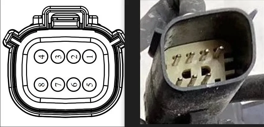
Now let's look at the factory LED (Harness Plug & Headlight Connector)
Note: Pin #6 is filled, and Pin #8 is missing
Power for the LED Headlamps is as follows from the BCM (As Built Data) Specific:
Low Beam:
Power = Pin #2
Ground = Pin #4
High Beam:
Power = Pin #3
Ground = Pin# 4
DRL:
Power = Pin #6 (LED Strip Bright)
Ground = Pin #4
Parking Lights:
Power = Pin #5 (LED Strip Dim)
Ground = Pin #4
Turn Signal:
Power = Pin # 7
Ground = Pin #1
Note: The LED Assemblies use the same dual filament bulb as the Halo housings use but it is only wire for Turn Signals, the Parking Light is moved to the LED strip that is shared with the DRL circuit. (This bulb and wire change is integral to the headlight housing)
Note: For the LED Pin #8 is missing on the Headlight Connector - this is a Ground that is spliced shared with Pin #4
EDIT: UPDATE 2/28/25
---
I wanted to confirm the power from the BCM with the (As Built) set for Lariat Trims and Factory LED Headlamps - Power Confirmed with meter
DRL:
Pin 6 (DRL) 12-Volts
Pins 2-3 & 5 = 0-Volts
Pin 7 (Turns) 12-Volts (Flashing) with turn (On)
Low Beam:
Pin 2 - (Low Beam) 12 -Volts
Pin 5 (Park) 12-Volts
Pin 3 (High Beam) = 0-Volts
Pin 6 (DRL) = 0-Volts
Pin 7 (Turns) 12-Volts (Flashing) with turn (On)
High Beam:
Pin 3 (High Beam) 12-Volts
Pin 2 (low Beam) = 0-Volts
Pin 5 (Park) 12-Volts
Pin 6 (DRL) = 0-Volts
Pin 7 (Turns) 12-Volts (Flashing) with turn (On)
Park (Only)
Pin 5 -(Park) 12-Volts
Pins 2 - 3 and 6 - = 0-Volts - Low Beam / High Beam & DRL
This circuit also flashes power when (Door Lock & Door Ajar) is triggered
So, this clearly shows how much of a difference the As-Built data changes power output from the BCM. Between the Halo & LED housings and the importance of changing the As-Builts.
---
End Of Update

So, even for Factory OE, it requires a change in the As-Built data to configure how the BCM supplies power (output) to the headlights between the Halo and LED configuration.
Thus, bring in the Aftermarket Lighting options and the requirement of them wanting you to use a (Fuse Tapped) Power Source.
The reason for them wanting this is simple - They CANNOT market a product and use the term (PLUG & PLAY) without it.
As they cannot market a product and then state (You MUST make changes to the As-Built Data Files) for them to work properly.
NOTE: The VAST MAJORITY of owners who upgrade are upgrading from HALO's.
Note: Above how the Halo's are pinned, and that Pin #6 is missing from the Halo (housing) and the factory BCM (As-Built) data is not producing a power output supply on that circuit.
This is the sole reason for the Tapped Power Source, it is NOT REQUIRED, but you MUST make the changes in Forscan to tell the BCM to power the headlamps as LED and not Halo's. (DRL Circuit) and (The Low Beam Circuit) as without making changes the BCM is still providing power to the (Low Beam) circuit (Pin #2) as the BCM still is programed as such
EDIT - Update 2/28/25
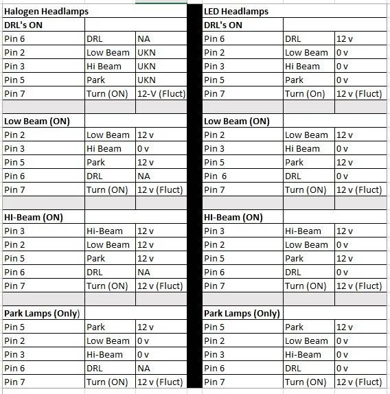
Here is a (Side By Side) Compare as I have for now for Power Output from the BCM.
This shows the importance of (Forscan) changes to get the BCM to properly power any headlamp that is installed.
I cannot get a valid - test of the DRL Circuit with the LED Housings Installed
I think the (issue) with not getting a valid test result is due to the BCM looking for a (Resistance) in the Low Beam Circuit (To Trigger) the DRL's to (ON), which I do not have (since) I have the LED assemblies installed.
The manuals for (DRL) T-Shoot only have you check for codes and ensure the (DRL) is enabled in the IPC and then has you go to the Low Beam circuit and Test for power with the (Headlamps -ON)
So, with Halogen Headlamps, there is not a specific wire check, so I am thinking that when the circuit is (Complete) the DRL's will enable, this takes the Halo's to be installed as a Back-Probe of the circuit to test it with LED assemblies installed or one or both connectors dis-connected the BCM sees this as an (OPEN) circuit
I think this (ISSUE) that I am having and found is transferring over to the LED Headlights and generating issues and this also leads me to believe that this is the primary reason for adding a (TAPPED) power source to get the DRL's to function correctly (without) any Forscan changes
The problem is: The BCM does not like that Tapped Power Source
If the Aftermarkets (Include) PIN #6 in the (Assembly Connector) then if I am correct the Tapped Power Sorce is (NOT NEEDED) and you only need to make the changes in Forscan for them to function (as if they were the Factory LED's)
If there is not a Pin 6 - in the (Assembly Connector) then instead of tapping a fused power source, one may try (Wire Tapping) the Pin #6 (DRL Wire) on the harness side and connect it to the (Assembly Harness) they have set up for the Fused Power Source, this way all you need to do is set up the As-Built files for the factory LED Housings, and they SHOULD function normally.
The Only (Unknown) is what specific circuit does each aftermarket (Tap Fused Power - For)
Is it the DRL Circuit or Low Beam or Park Lamp - They all call it the DRL but is it truly the (BCM-Pin #6 DRL Circuit.
As this will affect the (extra's) - Start Up Sequence, Sequential Turns Etc.
BCM Power Output Compare - Halo vs LED
As-Built Data (Specific) between Halo & LED adjusts Power Outputs to the Lights
Note: Halo Housings do NOT Have Pin #6 for the Dedicated DRL Circuit as the DRL circuit powers off of the Low Beam circuit.
Note: The Indicated 12-Volts is actually full battery voltage (Charging) so any voltage volage reading in the charging voltage range is normal and is (normally noted) as 12 -Volts

----
END of Update
Aftermarket Options:
Section 1 - Morimoto's
Per the Online Video provided by (Headlight Revolution)
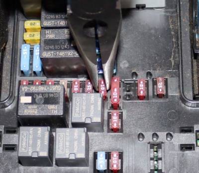
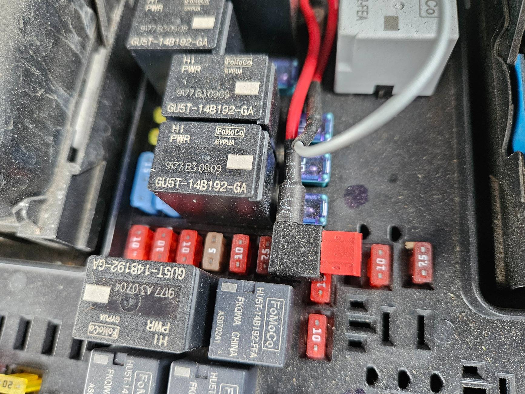
Fuse Tap the DRL Wire (Blue) to Fuse #19 (Switched Power)
Option (Connector) for Sequential or Standard Turn Signal (Blink/Flash) - Connected = Sequential / Disconnected = Standard
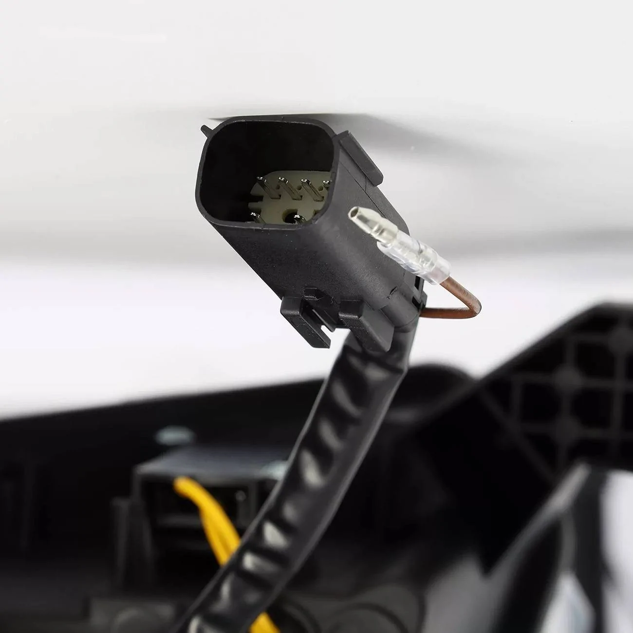
The UNKNOWNs as of this writing as I can find no detailed install info (PDF) for how the connector is wired (Component Side)
What pins if any are missing from the Headlight Connector? (IMPORTANT - Need to Know)
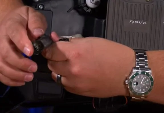
What is the (White Insulation) Wire for? Ref Pic Below
What Wire - in the connector is actually being (Fuse Tapped)? is this pin #6?
What circuit - is the trigger for the Start Up Sequence? is this pin #2 for Low Beam or another pin?
I am working on T-Shoot for issues with these lights, but I do not have the relevant info and seek help from members who have installed them or have a set (uninstalled) and a multi-meter to find the unanswered questions.
So, anyone who can provide any extra info here - please post

Best pic (screenshot) I can find of the Morimoto Connector (Cannot See what I need to know)

Due to the great number of issues members are having with all Aftermarket Headlights, I wanted to attempt to find a resolution and to bring a full understanding of how differ in wiring and why they push the use of tapping a power source.
I do not have aftermarkets, but I did swap my Lariat (LED) Deleted headlamps (Halo's) for Factory LED Headlamps & Fogs to bring it back to how it was ordered.
I used the As-Built data files and crossed checked (Halo & LED) in the As-Built files for various VIN's and found that all (Halo) and all (LED) were set up differently.
I took the LED Lariat settings and made the As-Built changes as needed in the BCM.
So, I know exactly all As-Built Data files that need changed to swap from Halo's to Factory LED's - Simple and work Flawlessly.
So, we will start with ALL Rangers are wired the same (for lighting) the change occurs at the Headlight Assemblies themselves and how they are pinned out at the Headlight (Component Side)
Here we have the Halo Headlight Connector (Harness Plug & Headlight Connector)
NOTE: Pin #6 is missing - this is due to the fact that the Halo's provide DRL Power to the Low Beam @ 50% Power
The BCM - is set the do this and no power is applied to PIN #6 (from the BCM to the Harness Connector)
Power for the Halo Headlamps from the BCM is as follows (As-Built Data) Specific:
I need to get my Forscan settings set back to OE (Halo) settings and actually VERIFY which of the following is TRUE
1. The BCM does not provide power on Pin #6 at all for the Halo (As-Built) settings
2. The BCM provides power to Pin #6 (Harness Side) but since it is deleted in the Headlight Connector - It Dead Ends
This is a valuable piece of information that is needed as this will truly tell me what the BCM is doing with power outputs.
Low Beam:
Power = Pin #2 (12 Volts)
Ground = Pin # 8
DRL:
Power = Pin #2 (6-Volts)
Ground = Pin # 8
High Beam:
Power = Pin #3
Ground = Pin #8
Parking Lights:
Power = Pin # 5
Ground = Pin # 1
Turn Signals:
Power = Pin # 7
Ground = Pin # 1
Ref: Note Pins 4 & 8 are spliced together (within the wire harness) Grounds
Halo Connector (Factory OE) - Pin #6 Missing on the Headlight (DRL-Circuit)
EDIT: UPDATE 2/28/25
---
I wanted to verify my above voltage (wire checks) for the factory Halo (BCM-As-Built) power
I reset all As-Builts back to Factory (OE) settings for the Halo's as they were installed.
DRL's (Only)
Initially I had 12 Volts on Pin 2 (Low Beam) and 12 Volts on Pin 5 (Park) but the sun was setting, and I think my Headlamps Triggered (ON)
Tried again (Today) in the full sun, no matter how I configured it, I could not get any power readings at all (When) DRL's should be on, I even tried back probing, DTC Resets, IPC selection (On & Off) and having both headlamp connectors off, the dash (IPC) indicated headlamps were off so DRL should be on (In Neutral/Drive)
I even tried (commanding them on with my scan tool)- got request cancelled.
Grr - So frustrating, with me having my (LED) headlamps installed and not having a visual indication for just (Low Beam) Bulbs its hard to tell.
I may have to revisit this
I am thinking that since I have LED Headlamps installed, its looking for resistance from the Low Beam (Bulb) which is not installed and the circuit is not activating, the only way to test this theory is to try to temp install the (Halo) on either side and test from the other - or put a resistor in the test circuit (Low Beam)
I think this (TEST) is SHOWING me, how the aftermarkets are responding, and the various issues members are getting
Low Beams (On)
Power on Pin 2 (Low Beam) 12 volts
Power on Pin 5 (Park Lamps) 12 volts
Pin 3 (High Beam) 0-Volts
Power on Pin 7 (Turns) Turn (ON) 12 Volts (Fluctuating)
High Beams (On)
Power on Pin 3 (High Beam) 12-Volts
Power on Pin 2 (Low Beam) 12-Volts
Power on Pin 5 (Park) 12-Volts
Power on Pin 7 (Turns) Turn (ON) 12 Volts (Fluctuating)
Park Lamps (Only)
Power on Pin 5 (Park) 12-Volts
Power on Pin 7 (Turns) Turn (ON) 12 Volts (Fluctuating)
Pin 2 and Pin 3 = 0-Volts (Low & High Beam)
So at least I know with this circuit (set-up) for High Beams it is pushing power to both circuits
---
End Of Update
Now let's look at the factory LED (Harness Plug & Headlight Connector)
Note: Pin #6 is filled, and Pin #8 is missing
Power for the LED Headlamps is as follows from the BCM (As Built Data) Specific:
Low Beam:
Power = Pin #2
Ground = Pin #4
High Beam:
Power = Pin #3
Ground = Pin# 4
DRL:
Power = Pin #6 (LED Strip Bright)
Ground = Pin #4
Parking Lights:
Power = Pin #5 (LED Strip Dim)
Ground = Pin #4
Turn Signal:
Power = Pin # 7
Ground = Pin #1
Note: The LED Assemblies use the same dual filament bulb as the Halo housings use but it is only wire for Turn Signals, the Parking Light is moved to the LED strip that is shared with the DRL circuit. (This bulb and wire change is integral to the headlight housing)
Note: For the LED Pin #8 is missing on the Headlight Connector - this is a Ground that is spliced shared with Pin #4
EDIT: UPDATE 2/28/25
---
I wanted to confirm the power from the BCM with the (As Built) set for Lariat Trims and Factory LED Headlamps - Power Confirmed with meter
DRL:
Pin 6 (DRL) 12-Volts
Pins 2-3 & 5 = 0-Volts
Pin 7 (Turns) 12-Volts (Flashing) with turn (On)
Low Beam:
Pin 2 - (Low Beam) 12 -Volts
Pin 5 (Park) 12-Volts
Pin 3 (High Beam) = 0-Volts
Pin 6 (DRL) = 0-Volts
Pin 7 (Turns) 12-Volts (Flashing) with turn (On)
High Beam:
Pin 3 (High Beam) 12-Volts
Pin 2 (low Beam) = 0-Volts
Pin 5 (Park) 12-Volts
Pin 6 (DRL) = 0-Volts
Pin 7 (Turns) 12-Volts (Flashing) with turn (On)
Park (Only)
Pin 5 -(Park) 12-Volts
Pins 2 - 3 and 6 - = 0-Volts - Low Beam / High Beam & DRL
This circuit also flashes power when (Door Lock & Door Ajar) is triggered
So, this clearly shows how much of a difference the As-Built data changes power output from the BCM. Between the Halo & LED housings and the importance of changing the As-Builts.
---
End Of Update
So, even for Factory OE, it requires a change in the As-Built data to configure how the BCM supplies power (output) to the headlights between the Halo and LED configuration.
Thus, bring in the Aftermarket Lighting options and the requirement of them wanting you to use a (Fuse Tapped) Power Source.
The reason for them wanting this is simple - They CANNOT market a product and use the term (PLUG & PLAY) without it.
As they cannot market a product and then state (You MUST make changes to the As-Built Data Files) for them to work properly.
NOTE: The VAST MAJORITY of owners who upgrade are upgrading from HALO's.
Note: Above how the Halo's are pinned, and that Pin #6 is missing from the Halo (housing) and the factory BCM (As-Built) data is not producing a power output supply on that circuit.
This is the sole reason for the Tapped Power Source, it is NOT REQUIRED, but you MUST make the changes in Forscan to tell the BCM to power the headlamps as LED and not Halo's. (DRL Circuit) and (The Low Beam Circuit) as without making changes the BCM is still providing power to the (Low Beam) circuit (Pin #2) as the BCM still is programed as such
EDIT - Update 2/28/25
Here is a (Side By Side) Compare as I have for now for Power Output from the BCM.
This shows the importance of (Forscan) changes to get the BCM to properly power any headlamp that is installed.
I cannot get a valid - test of the DRL Circuit with the LED Housings Installed
I think the (issue) with not getting a valid test result is due to the BCM looking for a (Resistance) in the Low Beam Circuit (To Trigger) the DRL's to (ON), which I do not have (since) I have the LED assemblies installed.
The manuals for (DRL) T-Shoot only have you check for codes and ensure the (DRL) is enabled in the IPC and then has you go to the Low Beam circuit and Test for power with the (Headlamps -ON)
So, with Halogen Headlamps, there is not a specific wire check, so I am thinking that when the circuit is (Complete) the DRL's will enable, this takes the Halo's to be installed as a Back-Probe of the circuit to test it with LED assemblies installed or one or both connectors dis-connected the BCM sees this as an (OPEN) circuit
I think this (ISSUE) that I am having and found is transferring over to the LED Headlights and generating issues and this also leads me to believe that this is the primary reason for adding a (TAPPED) power source to get the DRL's to function correctly (without) any Forscan changes
The problem is: The BCM does not like that Tapped Power Source
If the Aftermarkets (Include) PIN #6 in the (Assembly Connector) then if I am correct the Tapped Power Sorce is (NOT NEEDED) and you only need to make the changes in Forscan for them to function (as if they were the Factory LED's)
If there is not a Pin 6 - in the (Assembly Connector) then instead of tapping a fused power source, one may try (Wire Tapping) the Pin #6 (DRL Wire) on the harness side and connect it to the (Assembly Harness) they have set up for the Fused Power Source, this way all you need to do is set up the As-Built files for the factory LED Housings, and they SHOULD function normally.
The Only (Unknown) is what specific circuit does each aftermarket (Tap Fused Power - For)
Is it the DRL Circuit or Low Beam or Park Lamp - They all call it the DRL but is it truly the (BCM-Pin #6 DRL Circuit.
As this will affect the (extra's) - Start Up Sequence, Sequential Turns Etc.
BCM Power Output Compare - Halo vs LED
As-Built Data (Specific) between Halo & LED adjusts Power Outputs to the Lights
Note: Halo Housings do NOT Have Pin #6 for the Dedicated DRL Circuit as the DRL circuit powers off of the Low Beam circuit.
Note: The Indicated 12-Volts is actually full battery voltage (Charging) so any voltage volage reading in the charging voltage range is normal and is (normally noted) as 12 -Volts
----
END of Update
Aftermarket Options:
Section 1 - Morimoto's
Per the Online Video provided by (Headlight Revolution)
Fuse Tap the DRL Wire (Blue) to Fuse #19 (Switched Power)
Option (Connector) for Sequential or Standard Turn Signal (Blink/Flash) - Connected = Sequential / Disconnected = Standard
The UNKNOWNs as of this writing as I can find no detailed install info (PDF) for how the connector is wired (Component Side)
What pins if any are missing from the Headlight Connector? (IMPORTANT - Need to Know)
What is the (White Insulation) Wire for? Ref Pic Below
What Wire - in the connector is actually being (Fuse Tapped)? is this pin #6?
What circuit - is the trigger for the Start Up Sequence? is this pin #2 for Low Beam or another pin?
I am working on T-Shoot for issues with these lights, but I do not have the relevant info and seek help from members who have installed them or have a set (uninstalled) and a multi-meter to find the unanswered questions.
So, anyone who can provide any extra info here - please post
Best pic (screenshot) I can find of the Morimoto Connector (Cannot See what I need to know)
Sponsored
Last edited: